
User`s manual


- 29 - Hardware Installation
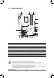
14) F_USB1/F_USB2/F_USB3 (USB 2.0/1.1 Headers)
TheheadersconformtoUSB2.0/1.1specication.EachUSBheadercanprovidetwoUSBportsviaan
optional USB bracket. For purchasing the optional USB bracket, please contact the local dealer.
Do not plug the IEEE 1394 bracket (2x5-pin) cable into the USB 2.0/1.1 header. •
Prior to installing the USB bracket, be sure to turn off your computer and unplug the power •
cord from the power outlet to prevent damage to the USB bracket.
When the system is in S4/S5 mode, only the USB ports routed to the F_USB1 header can sup-
port the ON/OFF Charge function.
DEBUG
PORT
G.QBOFM
10
9
2
1
Pin No. Denition
1 Power (5V)
2 Power (5V)
3 USB DX-
4 USB DY-
5 USB DX+
6 USB DY+
7 GND
8 GND
9 No Pin
10 NC
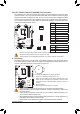
15) F_USB30 (USB 3.0/2.0 Header)
TheheaderconformstoUSB3.0/2.0specication.EachUSBheadercanprovidetwoUSBports.
Pin No. Denition Pin No. Denition
1 VBUS 11 D2+
2 SSRX1- 12 D2-
3 SSRX1+ 13 GND
4 GND 14 SSTX2+
5 SSTX1- 15 SSTX2-
6 SSTX1+ 16 GND
7 GND 17 SSRX2+
8 D1- 18 SSRX2-
9 D1+ 19 VBUS
10 NC 20 No Pin
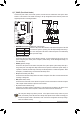
F_USB30
F_AUDIO(H)
DB_PORT
F_PANEL(NH) F_PANEL
(H61M-D2)
TPM
w/housing
10
11
20
1