GA-H61M-WW User's Manual Rev.
Motherboard GA-H61M-WW Motherboard GA-H61M-WW Jul. 5, 2013 Jul. 5, 2013 Copyright © 2013 GIGA-BYTE TECHNOLOGY CO., LTD. All rights reserved. The trademarks mentioned in this manual are legally registered to their respective owners. Disclaimer Information in this manual is protected by copyright laws and is the property of GIGABYTE. Changes to the specifications and features in this manual may be made by GIGABYTE without prior notice.
Table of Contents GA-H61M-WW Motherboard Layout................................................................................4 GA-H61M-WW Motherboard Block Diagram....................................................................5 Chapter 1 Hardware Installation......................................................................................6 1-1 1-2 1-3 1-4 1-5 1-6 1-7 Installation Precautions.....................................................................................
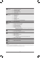
GA-H61M-WW Motherboard Layout KB_MS VGA LPT COMA ATX_12V LGA1155 ATX USB_LAN DDR3_1 CPU_FAN BAT AUDIO Realtek® GbE LAN GA-H61M-WW PCIEX16 PCIEX1 CI iTE® Super I/O DDR3_2 R_USB M_BIOS Intel® H61 SATA2 0 1 PCI CODEC F_AUDIO SYS_FAN CLR_CMOS F_PANEL 3 2 F_USB1 SPEAKER F_USB2 Box Contents 55 GA-H61M-WW motherboard 55 Motherboard driver disk 55 User's Manual 55 Two SATA cables 55 I/O Shield The box contents above are for reference only and the actual items shall depend on the product
GA-H61M-WW Motherboard Block Diagram 1 PCI Express x16 CPU CLK+/- (100 MHz) LGA1155 CPU x16 DMI 2.0 PCI Express Bus LAN RJ45 PCIe CLK (100 MHz) x1 BIOS x1 x1 Intel® H61 LPT LPC iTE® Bus Super I/O 1PCI Express x1 PCI Bus MIC (Center/Subwoofer Speaker Out) Line Out (Front Speaker Out) Line In (Rear Speaker Out) CODEC PCI CLK (33 MHz) 4 SATA 3Gb/s 8 USB 2.0/1.
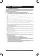
Chapter 1 1-1 Hardware Installation Installation Precautions The motherboard contains numerous delicate electronic circuits and components which can become damaged as a result of electrostatic discharge (ESD). Prior to installation, carefully read the user's manual and follow these procedures: •• Prior to installation, make sure the chassis is suitable for the motherboard. •• Prior to installation, do not remove or break motherboard S/N (Serial Number) sticker or warranty sticker provided by your dealer.
1-2 Product Specifications CPU Support for Intel® Core™ i7 processors/Intel® Core™ i5 processors/ Intel® Core™ i3 processors/Intel® Pentium® processors/Intel® Celeron® processors in the LGA1155 package (Go to GIGABYTE's website for the latest CPU support list.) L3 cache varies with CPU Chipset Intel® H61 Express Chipset Memory 2 x 1.
Internal Connectors Back Panel Connectors I/O Controller iTE® I/O Controller Chip Hardware Monitor BIOS 1 x front panel header 1 x front panel audio header 2 x USB 2.0/1.1 headers 1 x Clear CMOS jumper 1 x chassis intrusion header 1 x speaker header 1 x PS/2 keyboard port 1 x PS/2 mouse port 1 x D-Sub port 1 x parallel port 1 x serial port 4 x USB 2.0/1.
1-3 Installing the CPU Read the following guidelines before you begin to install the CPU: •• Make sure that the motherboard supports the CPU. (Go to GIGABYTE's website for the latest CPU support list.) •• Always turn off the computer and unplug the power cord from the power outlet before installing the CPU to prevent hardware damage. •• Locate the pin one of the CPU. The CPU cannot be inserted if oriented incorrectly.
1-5 Installing an Expansion Card Read the following guidelines before you begin to install an expansion card: •• Make sure the motherboard supports the expansion card. Carefully read the manual that came with your expansion card. •• Always turn off the computer and unplug the power cord from the power outlet before installing an expansion card to prevent hardware damage.
Mic In Jack (Pink) The default Mic in jack. Microphones must be connected to this jack. To configure 7.1-channel audio, you have to use an HD front panel audio module and enable the multi-channel audio feature through the audio driver.
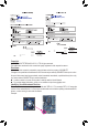
1/2) ATX_12V/ATX (2x2 12V Power Connector and 2x12 Main Power Connector) With the use of the power connector, the power supply can supply enough stable power to all the components on the motherboard. Before connecting the power connector, first make sure the power supply is turned off and all devices are properly installed. The power connector possesses a foolproof design. Connect the power supply cable to the power connector in the correct orientation.
DEBUG PORT DEBUG PORT DEBUG PORT 5) SATA2 0/1/2/3 (SATA 3Gb/s Connectors) The SATA connectors conform to SATA 3Gb/s standard and are compatible with SATA 1.5Gb/s standard. Each SATA connector supports a single SATA device. Pin No. 1 2 3 4 5 6 7 SATA2 1 7 1 7 1 0 1 7 2 3 Definition GND TXP TXN GND RXN RXP GND 6) F_PANEL (Front Panel Header) Connect the power switch, reset switch, and system status indicator on the chassis to this header according to the pin assignments below.
8) F_AUDIO (Front Panel Audio Header) The front panel audio header supports Intel® High Definition audio (HD) and AC'97 audio. You may connect your chassis front panel audio module to this header. Make sure the wire assignments of the module connector match the pin assignments of the motherboard header. Incorrect connection between the module connector and the motherboard header will make the device unable to work or even damage it. 10 9 2 1 For HD Front Panel Audio: Pin No.
11) BAT (Battery) The battery provides power to keep the values (such as BIOS configurations, date, and time information) in the CMOS when the computer is turned off. Replace the battery when the battery voltage drops to a low level, or the CMOS values may not be accurate or may be lost. You may clear the CMOS values by removing the battery: 1. Turn off your computer and unplug the power cord. 2. Gently remove the battery from the battery holder and wait for one minute.
2-1 Startup Screen The following startup Logo screen will appear when the computer boots. (Sample BIOS Version: E11) Function Keys On the main menu of the BIOS Setup program, press arrow keys to move among the items and press to accept or enter a sub-menu. Or you can use your mouse to select the item you want. •• When the system is not stable as usual, select the Load Optimized Defaults item to set your system to its defaults.
`` M.I.T. Current Status This screen provides information on CPU/memory frequencies/parameters. `` Advanced Frequency Settings && Processor Graphics Clock Allows you to set the onboard graphics clock. The adjustable range is from 400 MHz to 3200 MHz. && CPU Clock Ratio Allows you to alter the clock ratio for the installed CPU. The adjustable range is dependent on the CPU being installed. && CPU Frequency Displays the current operating CPU frequency.
&& CPU Thermal Monitor (Note 1) Enables or disables Intel® CPU Thermal Monitor function, a CPU overheating protection function. When enabled, the CPU core frequency and voltage will be reduced when the CPU is overheated. Auto lets the BIOS automatically configure this setting. (Default: Auto) && CPU EIST Function (Note 1) Enables or disables Enhanced Intel® SpeedStep Technology (EIST).
&& Rank Interleaving Enables or disables memory rank interleaving. Enabled allows the system to simultaneously access different ranks of the memory to increase memory performance and stability. Auto lets the BIOS automatically configure this setting. (Default: Auto) `` Channel A/B Timing Settings This sub-menu provides memory timing settings for each channel of memory. The respective timing setting screens are configurable only when DRAM Timing Selectable is set to Quick or Expert.
&& Slope PWM Allows you to control the CPU fan speed. This item is configurable only when CPU Fan Speed Control is set to Manual. Options are: 0.75 PWM value /oC ~ 2.50 PWM value /oC. && System Fan Speed Control Allows you to determine whether to enable the system fan speed control function and adjust the fan speed. Normal Allows the system fan to run at different speeds according to the system temperature. You can adjust the fan speed with EasyTune based on your system requirements.
&& Access Level Displays the current access level depending on the type of password protection used. (If no password is set, the default will display as Administrator.) The Administrator level allows you to make changes to all BIOS settings; the User level only allows you to make changes to certain BIOS settings but not all. `` ATA Port Information This section provides information on the device connected to each SATA port controlled by the Chipset.
&& Security Option Specifies whether a password is required every time the system boots, or only when you enter BIOS Setup. After configuring this item, set the password(s) under the Set Supervisor/User Password item in the BIOS Main Menu. Setup A password is only required for entering the BIOS Setup program. System A password is required for booting the system and for entering the BIOS Setup program.
&& Intel Virtualization Technology (Note) Enables or disables Intel® Virtualization Technology. Virtualization enhanced by Intel® Virtualization Technology will allow a platform to run multiple operating systems and applications in independent partitions. With virtualization, one computer system can function as multiple virtual systems. (Default: Disabled) && OS Type Allows you to select the operating system to be installed. Set this item to Windows 8 for Windows 8 operating system.
&& Administrator Password Allows you to configure an administrator password. Press on this item, type the password, and then press . You will be requested to confirm the password. Type the password again and press . You must enter the administrator password (or user password) at system startup and when entering BIOS Setup. Differing from the user password, the administrator password allows you to make changes to all BIOS settings.
2-5 Peripherals && SATA Controller(s) Enables or disables the integrated SATA controllers. (Default: Enabled) && SATA Mode Selection Allows you to decide whether to configure the SATA controller integrated in the Chipset to AHCI mode. IDE Configures the SATA controller to IDE mode. (Default) AHCI Configures the SATA controllers to AHCI mode.
&& Intel(R) Rapid Start Technology Enables or disables Intel® Rapid Start Technology. This item is configurable only when an SSD is installed. (Default: Disabled) && Legacy USB Support Allows USB keyboard/mouse to be used in MS-DOS. (Default: Enabled) && EHCI Hand-off Determines whether to enable EHCI Hand-off feature for an operating system without EHCI Hand-off support. (Default: Disabled) && Port 60/64 Emulation Enables or disables emulation of I/O ports 64h and 60h.
2-6 Power Management && Resume by Alarm Determines whether to power on the system at a desired time. (Default: Disabled) If enabled, set the date and time as following: Wake up day: Turn on the system at a specific time on each day or on a specific day in a month. Wake up hour/minute/second: Set the time at which the system will be powered on automatically.
&& Power On By Keyboard Allows the system to be turned on by a PS/2 keyboard wake-up event. Note: To use this function, you need an ATX power supply providing at least 1A on the +5VSB lead. Disabled Disables this function. (Default) Password Set a password with 1~5 characters to turn on the system. Keyboard 98 Press POWER button on the Windows 98 keyboard to turn on the system. Any Key Press any key to turn on the system.
&& Save & Exit Setup Press on this item and select Yes. This saves the changes to the CMOS and exits the BIOS Setup program. Select No or press to return to the BIOS Setup Main Menu. && Exit Without Saving Press on this item and select Yes. This exits the BIOS Setup without saving the changes made in BIOS Setup to the CMOS. Select No or press to return to the BIOS Setup Main Menu.
Regulatory Statements Regulatory Notices This document must not be copied without our written permission, and the contents there of must not be imparted to a third party nor be used for any unauthorized purpose. Contravention will be prosecuted. We believe that the information contained herein was accurate in all respects at the time of printing. GIGABYTE cannot, however, assume any responsibility for errors or omissions in this text.
- 31 -
Contact Us GIGA-BYTE TECHNOLOGY CO., LTD. Address: No.6, Bao Chiang Road, Hsin-Tien Dist., New Taipei City 231,Taiwan TEL: +886-2-8912-4000, FAX: +886-2-8912-4005 Tech. and Non-Tech. Support (Sales/Marketing) : http://ggts.gigabyte.com.tw WEB address (English): http://www.gigabyte.com WEB address (Chinese): http://www.gigabyte.tw You may go to the GIGABYTE website, select your language in the language list on the top right corner of the website.