GA-H61M-USB3H User's Manual Rev.
Motherboard GA-H61M-USB3H Motherboard GA-H61M-USB3H Mar. 8, 2013 Mar. 8, 2013 Copyright © 2013 GIGA-BYTE TECHNOLOGY CO., LTD. All rights reserved. The trademarks mentioned in this manual are legally registered to their respective owners. Disclaimer Information in this manual is protected by copyright laws and is the property of GIGABYTE. Changes to the specifications and features in this manual may be made by GIGABYTE without prior notice.
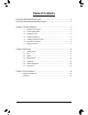
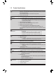
Table of Contents GA-H61M-USB3H Motherboard Layout...........................................................................4 GA-H61M-USB3H Motherboard Block Diagram...............................................................5 Chapter 1 Hardware Installation......................................................................................6 1-1 Installation Precautions..................................................................................... 6 1-2 Product Specifications..............
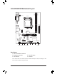
DDR3_1 KB_MS_USB ATX_12V DDR3_2 GA-H61M-USB3H Motherboard Layout LGA1155 DVI_VGA HDMI ATX R_USB30 USB_LAN CPU_FAN BAT AUDIO M_BIOS CODEC B_BIOS GA-H61M-USB3H PCIEX16 VIA VL805 PCIEX1 SYS_FAN CI iTE Super I/O Realtek GbE LAN Intel® H61 CLR_CMOS SPEAKER 3 2 1 0 SATA2 F_AUDIO F_USB2 F_USB1 F_USB30 F_PANEL Box Contents 55 GA-H61M-USB3H motherboard 55 Motherboard driver disk 55 User's Manual 55 Two SATA cables 55 I/O Shield The box contents above are for reference only and the actua
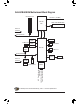
GA-H61M-USB3H Motherboard Block Diagram 1 PCI Express x16 CPU CLK+/- (100 MHz) LGA1155 CPU DDR3 1333/1066/800 MHz Dual Channel Memory DMI 2.0 x16 PCI Express Bus Dual BIOS D-Sub 4 USB 3.0/2.0 FDI PCIe CLK (100 MHz) DVI-D 4 SATA 3Gb/s HDMI VIA VL805 PCI Express Bus 8 USB 2.0/1.
Chapter 1 Hardware Installation 1-1 Installation Precautions The motherboard contains numerous delicate electronic circuits and components which can become damaged as a result of electrostatic discharge (ESD). Prior to installation, carefully read the user's manual and follow these procedures: •• Prior to installation, make sure the chassis is suitable for the motherboard. •• Prior to installation, do not remove or break motherboard S/N (Serial Number) sticker or warranty sticker provided by your dealer.
1-2 Product Specifications CPU Support for Intel® Core™ i7 processors/Intel® Core™ i5 processors/ Intel® Core™ i3 processors/Intel® Pentium® processors/Intel® Celeron® processors in the LGA1155 package (Go to GIGABYTE's website for the latest CPU support list.) L3 cache varies with CPU Chipset Intel® H61 Express Chipset Memory 2 x 1.
Internal Connectors Back Panel Connectors 1 x system fan header 1 x front panel header 1 x front panel audio header 1 x speaker header 1 x USB 3.0/2.0 header 2 x USB 2.0/1.1 headers 1 x chassis intrusion header 1 x Clear CMOS jumper 1 x PS/2 keyboard/mouse port 1 x D-Sub port 1 x DVI-D port 1 x HDMI port 2 x USB 3.0/2.0 ports 4 x USB 2.0/1.
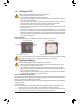
1-3 Installing the CPU Read the following guidelines before you begin to install the CPU: •• Make sure that the motherboard supports the CPU. (Go to GIGABYTE's website for the latest CPU support list.) •• Always turn off the computer and unplug the power cord from the power outlet before installing the CPU to prevent hardware damage. •• Locate the pin one of the CPU. The CPU cannot be inserted if oriented incorrectly.
1-5 Installing an Expansion Card Read the following guidelines before you begin to install an expansion card: •• Make sure the motherboard supports the expansion card. Carefully read the manual that came with your expansion card. •• Always turn off the computer and unplug the power cord from the power outlet before installing an expansion card to prevent hardware damage. 1-6 Back Panel Connectors USB 2.0/1.1 Port The USB port supports the USB 2.0/1.1 specification.
Line In Jack (Blue) The default line in jack. Use this audio jack for line in devices such as an optical drive, walkman, etc. Line Out Jack (Green) The default line out jack. Use this audio jack for a headphone or 2-channel speaker. This jack can be used to connect front speakers in a 4/5.1/7.1-channel audio configuration. Mic In Jack (Pink) The default Mic in jack. Microphones must be connected to this jack. To configure 7.
1/2) ATX_12V/ATX (2x2 12V Power Connector and 2x12 Main Power Connector) With the use of the power connector, the power supply can supply enough stable power to all the components on the motherboard. Before connecting the power connector, first make sure the power supply is turned off and all devices are properly installed. The power connector possesses a foolproof design. Connect the power supply cable to the power connector in the correct orientation.
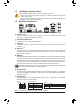
DEBUG PORT DEBUG PORT DEBUG PORT 5) SATA2 0/1/2/3 (SATA 3Gb/s Connectors) The SATA connectors conform to SATA 3Gb/s standard and are compatible with SATA 1.5Gb/s standard. Each SATA connector supports a single SATA device. Pin No. 1 2 3 4 5 6 7 SATA2 7 1 3 1 7 2 1 0 Definition GND TXP TXN GND RXN RXP GND 6) F_PANEL (Front Panel Header) Connect the power switch, reset switch, and system status indicator on the chassis to this header according to the pin assignments below.
B ( P 8) F_AUDIO (Front Panel Audio Header) 1 2 PWM Switch (X58A-OC) 1 2 3 1 Definition USB DY+ GND GND No Pin NC 1 DIP 1 10 20 11 Pin No. 1 2 3 4 5 6 7 8 9 10 Definition VBUS SSRX1SSRX1+ GND SSTX1SSTX1+ GND D1D1+ NC Pin No. 11 12 13 14 15 16 17 18 19 20 Definition D2+ D2GND SSTX2+ SSTX2GND SSRX2+ SSRX2VBUS No Pin Voltage measurement points(G1.Sniper 3) The header conforms to USB 3.0/2.0 specification and can provide two USB ports. For purchasing the optional 3.
11) CLR_CMOS (Clear CMOS Jumper) Use this jumper to clear the CMOS values (e.g. date information and BIOS configurations) and reset the CMOS values to factory defaults. To clear the CMOS values, use a metal object like a screwdriver to touch the two pins for a few seconds. Open: Normal Short: Clear CMOS Values •• Always turn off your computer and unplug the power cord from the power outlet before clearing the CMOS values.
Chapter 2 BIOS Setup BIOS (Basic Input and Output System) records hardware parameters of the system in the CMOS on the motherboard. Its major functions include conducting the Power-On Self-Test (POST) during system startup, saving system parameters and loading operating system, etc. BIOS includes a BIOS Setup program that allows the user to modify basic system configuration settings or to activate certain system features.
2-2 M.I.T. This section provides information on the BIOS version, CPU base clock, CPU frequency, memory frequency, total memory size, CPU temperature, Vcore, and memory voltage. Whether the system will work stably with the overclock/overvoltage settings you made is dependent on your overall system configurations. Incorrectly doing overclock/overvoltage may result in damage to CPU, chipset, or memory and reduce the useful life of these components.
&& Turbo Power Limit (Watts) Allows you to set a power limit for CPU Turbo mode. When the CPU power consumption exceeds the specified power limit, the CPU will automatically reduce the core frequency in order to reduce the power. Auto sets the power limit according to the CPU specifications. (Default: Auto) && Core Current Limit (Amps) Allows you to set a current limit for CPU Turbo mode.
`` Advanced Memory Settings && Extreme Memory Profile (X.M.P.) (Note), System Memory Multiplier, Memory Frequency(MHz) The settings above are synchronous to those under the same items on the Advanced Frequency Settings menu. && Performance Enhance Allows the system to operate at three different performance levels. Normal Lets the system operate at its basic performance level. Turbo Lets the system operate at its good performance level.
&& CPU Vcore/Dram Voltage/+5V/+12V/CPU VTT Displays the current system voltages. Displays current CPU/system temperature. Displays current CPU/system fan speeds. Sets the warning threshold for CPU temperature. When CPU temperature exceeds the threshold, BIOS will emit warning sound. Options are: Disabled (default), 60oC/140oF, 70oC/158oF, 80oC/176oF, 90oC/194oF.
2-3 System This section provides information on your motherboard model and BIOS version. You can also select the default language used by the BIOS and manually set the system time. && System Language Selects the default language used by the BIOS. Sets the system date. The date format is week (read-only), month, date, and year. Use to switch between the Month, Date, and Year fields and use the or key to set the desired value.
2-4 BIOS Features && Boot Option Priorities Specifies the overall boot order from the available devices. For example, you can set hard drive as the first priority (Boot Option #1) and DVD ROM drive as the second priority (Boot Option #2). The list only displays the device with the highest priority for a specific type. For example, only hard drive defined as the first priority on the Hard Drive BBS Priorities submenu will be presented here.
&& Execute Disable Bit (Note) Enables or disables Intel Execute Disable Bit function. This function may enhance protection for the computer, reducing exposure to viruses and malicious buffer overflow attacks when working with its supporting software and system. (Default: Enabled) && Intel Virtualization Technology (Note) Enables or disables Intel Virtualization Technology.
&& Administrator Password Allows you to configure an administrator password. Press on this item, type the password, and then press . You will be requested to confirm the password. Type the password again and press . You must enter the administrator password (or user password) at system startup and when entering BIOS Setup. Differing from the user password, the administrator password allows you to make changes to all BIOS settings.
&& Init Display First Specifies the first initiation of the monitor display from the installed PCI Express graphics card or the onboard graphics. Auto Lets BIOS automatically configure this setting. (Default) IGFX Sets the onboard graphics as the first display. PEG Sets the PCI Express graphics card on the PCIEX16 slot as the first display. && Internal Graphics Enables or disables the onboard graphics function. (Default: Auto) Allows you to set the onboard graphics memory size.
2-6 Power Management && Resume by Alarm Determines whether to power on the system at a desired time. (Default: Disabled) If enabled, set the date and time as following: Wake up day: Turn on the system at a specific time on each day or on a specific day in a month. Wake up hour/minute/second: Set the time at which the system will be powered on automatically.
&& AC BACK Determines the state of the system after the return of power from an AC power loss. Memory The system returns to its last known awake state upon the return of the AC power. Always On The system is turned on upon the return of the AC power. Always Off The system stays off upon the return of the AC power. (Default) && Power On By Keyboard Allows the system to be turned on by a PS/2 keyboard wake-up event.
&& Save & Exit Setup Press on this item and select Yes. This saves the changes to the CMOS and exits the BIOS Setup program. Select No or press to return to the BIOS Setup Main Menu. && Exit Without Saving Press on this item and select Yes. This exits the BIOS Setup without saving the changes made in BIOS Setup to the CMOS. Select No or press to return to the BIOS Setup Main Menu.
Regulatory Statements Regulatory Notices This document must not be copied without our written permission, and the contents there of must not be imparted to a third party nor be used for any unauthorized purpose. Contravention will be prosecuted. We believe that the information contained herein was accurate in all respects at the time of printing. GIGABYTE cannot, however, assume any responsibility for errors or omissions in this text.
- 30 -
- 31 -
Contact Us GIGA-BYTE TECHNOLOGY CO., LTD. Address: No.6, Bao Chiang Road, Hsin-Tien Dist., New Taipei City 231,Taiwan TEL: +886-2-8912-4000, FAX: +886-2-8912-4003 Tech. and Non-Tech. Support (Sales/Marketing) : http://ggts.gigabyte.com.tw WEB address (English): http://www.gigabyte.com WEB address (Chinese): http://www.gigabyte.tw You may go to the GIGABYTE website, select your language in the language list on the top right corner of the website.