GA-H61M-S2P-B3 User's Manual Rev.
Motherboard GA-H61M-S2P-B3 Jun. 10, 2011 GA-H61M-S2P-B3 Motherboard Jun.
Copyright © 2011 GIGA-BYTE TECHNOLOGY CO., LTD. All rights reserved. The trademarks mentioned in this manual are legally registered to their respective owners. Disclaimer Information in this manual is protected by copyright laws and is the property of GIGABYTE. Changes to the specifications and features in this manual may be made by GIGABYTE without prior notice.
Table of Contents GA-H61M-S2P-B3 Motherboard Layout..........................................................................5 GA-H61M-S2P-B3 Motherboard Block Diagram.............................................................6 Chapter 1 Hardware Installation......................................................................................7 1-1 1-2 1-3 1-4 1-5 1-6 1-7 Installation Precautions.................................................................................... 7 Product Specifications.
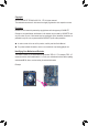
GA-H61M-S2P-B3 Motherboard Layout KB_MS COM ATX_12V VGA LPT LGA1155 CPU_FAN ATX R_USB Atheros AR8151 USB_LAN iTE IT8728 DDR3_1 PCI1 M_BIOS GA-H61M-S2P-B3 DDR3_2 BAT PCIEX16 B_BIOS PCIe to PCI Bridge AUDIO Intel® H61 PCI2 SATA2_0 CODEC F_AUDIO PCIEX1 SYS_FAN SATA2_1 CLR_CMOS F_USB2 F_USB1 F_PANEL SATA2_2 SATA2_3 Box Contents GA-H61M-S2P-B3 motherboard Motherboard driver disk User's Manual Two SATA cables I/O Shield * The box contents above are for reference only and the actua
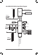
GA-H61M-S2P-B3 Motherboard Block Diagram 1 PCI Express x16 CPU CLK+/- (100 MHz) LGA1155 CPU DDR3 1333/1066/800 MHz Dual Channel Memory DMI 2.0 x16 PCI Express Bus FDI PCIe CLK (100 MHz) Dual BIOS D-Sub 4 SATA 3Gb/s PCI Express Bus PCIe CLK (100 MHz) x1 1 PCI Express x1 x1 Atheros AR8151 x1 Intel® H61 8 USB 2.0/1.
Chapter 1 1-1 Hardware Installation Installation Precautions The motherboard contains numerous delicate electronic circuits and components which can become damaged as a result of electrostatic discharge (ESD). Prior to installation, carefully read the user's manual and follow these procedures: •• Prior to installation, do not remove or break motherboard S/N (Serial Number) sticker or warranty sticker provided by your dealer. These stickers are required for warranty validation.
1-2 Product Specifications CPU Support for Intel® Core™ i7 processors/Intel® Core™ i5 processors/ Intel® Core™ i3 processors/Intel® Pentium® processors/Intel® Celeron® processors in the LGA1155 package (Go to GIGABYTE's website for the latest CPU support list.) L3 cache varies with CPU Chipset Intel® H61 Express Chipset Memory 2 x 1.
Back Panel Connectors 1 x PS/2 keyboard port 1 x PS/2 mouse port 1 x parallel port 1 x serial port 1 x D-Sub port 4 x USB 2.0/1.
1-3 Installing the CPU and CPU Cooler Read the following guidelines before you begin to install the CPU: •• Make sure that the motherboard supports the CPU. (Go to GIGABYTE's website for the latest CPU support list.) •• Always turn off the computer and unplug the power cord from the power outlet before installing the CPU to prevent hardware damage. •• Locate the pin one of the CPU. The CPU cannot be inserted if oriented incorrectly.
1-4 Installing the Memory Read the following guidelines before you begin to install the memory: •• Make sure that the motherboard supports the memory. It is recommended that memory of the same capacity, brand, speed, and chips be used. (Go to GIGABYTE's website for the latest supported memory speeds and memory modules.) •• Always turn off the computer and unplug the power cord from the power outlet before installing the memory to prevent hardware damage. •• Memory modules have a foolproof design.
1-6 Back Panel Connectors PS/2 Keyboard and PS/2 Mouse Port Use the upper port (green) to connect a PS/2 mouse and the lower port (purple) to connect a PS/2 keyboard. Parallel Port Use the parallel port to connect devices such as a printer, scanner and etc. The parallel port is also called a printer port. Serial Port Use the serial port to connect devices such as a mouse, modem or other peripherals. D-Sub Port The D-Sub port supports a 15-pin D-Sub connector.
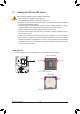
1-7 Internal Connectors 1 3 2 10 5 7 1) 2) 3) 4) 5) ATX_12V ATX CPU_FAN SYS_FAN SATA2_0/1/2/3 4 8 6) 7) 8) 9) 10) 9 6 F_PANEL F_AUDIO F_USB1/F_USB2 CLR_CMOS BAT Read the following guidelines before connecting external devices: •• First make sure your devices are compliant with the connectors you wish to connect. •• Before installing the devices, be sure to turn off the devices and your computer. Unplug the power cord from the power outlet to prevent damage to the devices.
1/2) ATX_12V/ATX (2x2 12V Power Connector and 2x12 Main Power Connector) With the use of the power connector, the power supply can supply enough stable power to all the components on the motherboard. Before connecting the power connector, first make sure the power supply is turned off and all devices are properly installed. The power connector possesses a foolproof design. Connect the power supply cable to the power connector in the correct orientation.
3/4) CPU_FAN/SYS_FAN (Fan Headers) The motherboard has a 4-pin CPU fan header (CPU_FAN), a 4-pin system fan header (SYS_FAN). Most fan headers possess a foolproof insertion design. When connecting a fan cable, be sure to connect it in the correct orientation (the black connector wire is the ground wire). The motherboard supports CPU fan speed control, which requires the use of a CPU fan with fan speed control design.
6) F_PANEL (Front Panel Header) Connect the power switch, reset switch, speaker, chassis intrusion switch/sensor and system status indicator on the chassis to this header according to the pin assignments below. Note the positive and negative pins before connecting the cables. Power Switch Hard Drive Reset Activity LED Switch SPEAK- Power LED Chassis Intrusion Header •• MSG/PWR (Message/Power/Sleep LED): Connects to the power status indicator on the chassis front panel.
7) F_AUDIO (Front Panel Audio Header) The front panel audio header supports Intel High Definition audio (HD) and AC'97 audio. You may connect your chassis front panel audio module to this header. Make sure the wire assignments of the module connector match the pin assignments of the motherboard header. Incorrect connection between the module connector and the motherboard header will make the device unable to work or even damage it. 2 1 10 9 For HD Front Panel Audio: Pin No.
9) CLR_CMOS (Clearing CMOS Jumper) Use this jumper to clear the CMOS values (e.g. date information and BIOS configurations) and reset the CMOS values to factory defaults. To clear the CMOS values, place a jumper cap on the two pins to temporarily short the two pins or use a metal object like a screwdriver to touch the two pins for a few seconds. Open: Normal Short: Clear CMOS Values •• Always turn off your computer and unplug the power cord from the power outlet before clearing the CMOS values.
Chapter 2 BIOS Setup To access the BIOS Setup program, press the key during the POST when the power is turned on. To see more advanced BIOS Setup menu options, you can press + in the main menu of the BIOS Setup program. To upgrade the BIOS, use either the GIGABYTE Q-Flash or @BIOS utility. •• Q-Flash allows the user to quickly and easily upgrade or back up BIOS without entering the operating system.
2-2 The Main Menu Once you enter the BIOS Setup program, the Main Menu (as shown below) appears on the screen. Use arrow keys to move among the items and press to accept or enter a sub-menu. (Sample BIOS Version: E2) CMOS Setup Utility-Copyright (C) 1984-2011 Award Software MB Intelligent Tweaker(M.I.T.
2-3 MB Intelligent Tweaker(M.I.T.) CMOS Setup Utility-Copyright (C) 1984-2011 Award Software MB Intelligent Tweaker(M.I.T.) } } } } } M.I.T Current Status Advanced Frequency Settings Advanced Memory Settings Advanced Voltage Settings Miscellaneous Settings BIOS Version BCLK CPU Frequency Memory Frequency Total Memory Size E2 99.80 MHz 3193.73 MHz 1330.76 MHz 1024 MB CPU Temperature 33oC Vcore DRAM Voltage 1.200 V 1.
`` M.I.T. Current Status This screen provides information on CPU/memory frequencies/parameters. `` Advanced Frequency Settings CMOS Setup Utility-Copyright (C) 1984-2011 Award Software Advanced Frequency Settings CPU Clock Ratio CPU Frequency } Advanced CPU Core Features >>>>> Standard Clock Control System Memory Multiplier (SPD) Memory Frequency (Mhz) 1333 Internal Graphics Clock 1100 Enter: Select : Move F5: Previous Values Item Help Menu Level [31X] 3.
Intel(R) Turbo Boost Tech. (Note) Allows you to determine whether to enable the Intel CPU Turbo Boost technology. Auto lets the BIOS automatically configure this setting. (Default: Auto) Turbo Ratio (1-Core)/(2-Core)/(3-Core)/(4-Core) (Note) Allows you to set the CPU Turbo ratios for different number of active cores. Auto sets the CPU Turbo ratios according to the CPU specifications. (Default: Auto) Turbo Power Limit (Watts) Allows you to set a power limit for CPU Turbo mode.
Bi-Directional PROCHOT (Note) Auto Lets the BIOS automatically configure this setting. (Default) Enabled When the CPU or chipset detects that an overheating is occurring, PROCHOT signals will be emitted to lower CPU performance to decrease heat production. Disabled Only allows the CPU to detect whether an overheating is occurring to emit PROCHOT signals. >>>>> Standard Clock Control System Memory Multiplier (SPD) Allows you to set the system memory multiplier.
DRAM Timing Selectable (SPD) Quick and Expert allows the Channel Interleaving, Rank Interleaving, Channel A Timing Settings, and Channel B Timing Settings items to be configurable. Options are: Auto (default), Quick, Expert. Profile DDR Voltage Displays the memory voltage as 1.5V. Profile VTT Voltage The value displayed here is dependent on the CPU being used. Channel Interleaving Enables or disables memory channel interleaving.
tRRD Options are: Auto (default), 1~15. tWTR Options are: Auto (default), 1~15. tWR Options are: Auto (default), 1~16. tWTP Options are: Auto (default), 1~31. tWL Options are: Auto (default), 1~12 tRFC Options are: Auto (default), 1~255. tRTP Options are: Auto (default), 1~15. tFAW Options are: Auto (default), 1~63. Command Rate(CMD) Options are: Auto (default), 1~3. >>>>> Channel A/B Misc Timing Control IO Latency Options are: Auto (default), 1~31.
DRAM Voltage The default is Auto. Miscellaneous Settings CMOS Setup Utility-Copyright (C) 1984-2011 Award Software Miscellaneous Settings Isochronous Support Virtualization Technology (Note) Enter: Select : Move F5: Previous Values Item Help Menu Level [Enabled] [Enabled] +/-/PU/PD: Value F10: Save F6: Fail-Safe Defaults ESC: Exit F1: General Help F7: Optimized Defaults Isochronous Support Determines whether to enable specific streams within the CPU and Chipset.
•• Manual Allows you to manually enter the specifications of the hard drive when the hard drive access mode is set to CHS. Access Mode Sets the hard drive access mode. Options are: Auto (default), CHS, LBA, Large. IDE Channel 2, 3 Master Extended IDE Drive Configure your SATA devices by using one of the two methods below: •• Auto Lets the BIOS automatically detect SATA devices during the POST.
Quick Boot Enables or disables the quick boot function to speed up the system boot-up process to shorten the waiting time for entering the operating system and to deliver greater efficiency for daily use. The settings here synchronize with the settings of the SMART QuickBoot of Smart 6™. (Default: Disabled) EFI CD/DVD Boot Option Set this item to EFI if you want to install the operating system to a hard drive larger than 2.2 TB.
Onboard VGA Enables or disables the onboard graphics function. Enable If No Ext PEG Activates the onboard graphics only when no PCI Express graphics card is installed. (Default) Always Enable Always activates the onboard graphics, whether or not a PCI Express graphics card is installed. If you wish to set up a dual-display configuration, set this item to Always Enable. On-Chip Frame Buffer Size Frame buffer size is the total amount of system memory allocated solely for the onboard graphics controller.
Azalia Codec Enables or disables the onboard audio function. (Default: Auto) If you wish to install a 3rd party add-in audio card instead of using the onboard audio, set this item to Disabled. Onboard H/W LAN Enables or disables the onboard LAN function. (Default: Enabled) If you wish to install a 3rd party add-in network card instead of using the onboard LAN, set this item to Disabled. Onboard LAN Boot ROM Allows you to decide whether to activate the boot ROM integrated with the onboard LAN chip.
Soft-Off by PWR-BTTN Configures the way to turn off the computer in MS-DOS mode using the power button. Instant-Off Press the power button and then the system will be turned off instantly. (Default) Delay 4 Sec. Press and hold the power button for 4 seconds to turn off the system. If the power button is pressed for less than 4 seconds, the system will enter suspend mode. PME Event Wake Up Allows the system to be awakened from an ACPI sleep state by a wake-up signal from a PCI or PCIe device.
AC Back Function Determines the state of the system after the return of power from an AC power loss. Soft-Off The system stays off upon the return of the AC power. (Default) Full-On The system is turned on upon the return of the AC power. Memory The system returns to its last known awake state upon the return of the AC power. ErP Support Determines whether to let the system consume less than 1W power in S5 (shutdown) state.
CPU Warning Temperature Sets the warning threshold for CPU temperature. When CPU temperature exceeds the threshold, BIOS will emit warning sound. Options are: Disabled (default), 60oC/140oF, 70oC/158oF, 80oC/176oF, 90oC/194oF. CPU/SYSTEM FAN Fail Warning Allows the system to emit warning sound if the CPU/system fan is not connected or fails. Check the fan condition or fan connection when this occurs.
2-10 Load Optimized Defaults CMOS Setup Utility-Copyright (C) 1984-2011 Award Software MB Intelligent Tweaker(M.I.T.
2-12 Save & Exit Setup CMOS Setup Utility-Copyright (C) 1984-2011 Award Software MB Intelligent Tweaker(M.I.T.
Chapter 3 Drivers Installation •• Before installing the drivers, first install the operating system. •• After installing the operating system, insert the motherboard driver disk into your optical drive. The driver Autorun screen is automatically displayed which looks like that shown in the screen shot below. (If the driver Autorun screen does not appear automatically, go to My Computer, double-click the optical drive and execute the Run.exe program.
BIOS Setup - 38 -
- 39 - BIOS Setup
Contact Us GIGA-BYTE TECHNOLOGY CO., LTD. Address: No.6, Bao Chiang Road, Hsin-Tien Dist., New Taipei City 231,Taiwan TEL: +886-2-8912-4000, FAX: +886-2-8912-4003 Tech. and Non-Tech. Support (Sales/Marketing) : http://ggts.gigabyte.com.tw WEB address (English): http://www.gigabyte.com WEB address (Chinese): http://www.gigabyte.tw You may go to the GIGABYTE website, select your language in the language list on the top right corner of the website.