
User`s manual

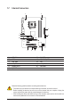
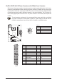
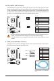


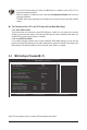
Table Of Contents
- GA-G41MT-S2 Motherboard Layout
- Chapter 1 Hardware Installation
- Chapter 2 BIOS Setup
- 2-1 Startup Screen
- 2-2 The Main Menu
- 2-3 MB Intelligent Tweaker(M.I.T.)
- 2-4 Standard CMOS Features
- 2-5 Advanced BIOS Features
- 2-6 Advanced Chipset Features
- 2-7 Integrated Peripherals
- 2-8 Power Management Setup
- 2-9 PnP/PCI Configurations
- 2-10 PC Health Status
- 2-11 Load Fail-Safe Defaults
- 2-12 Load Optimized Defaults
- 2-13 Set Supervisor/User Password
- 2-14 Save & Exit Setup
- 2-15 Exit Without Saving
- Chapter 3 Drivers Installation
- Regulatory Statements
- 17 - Hardware Installation
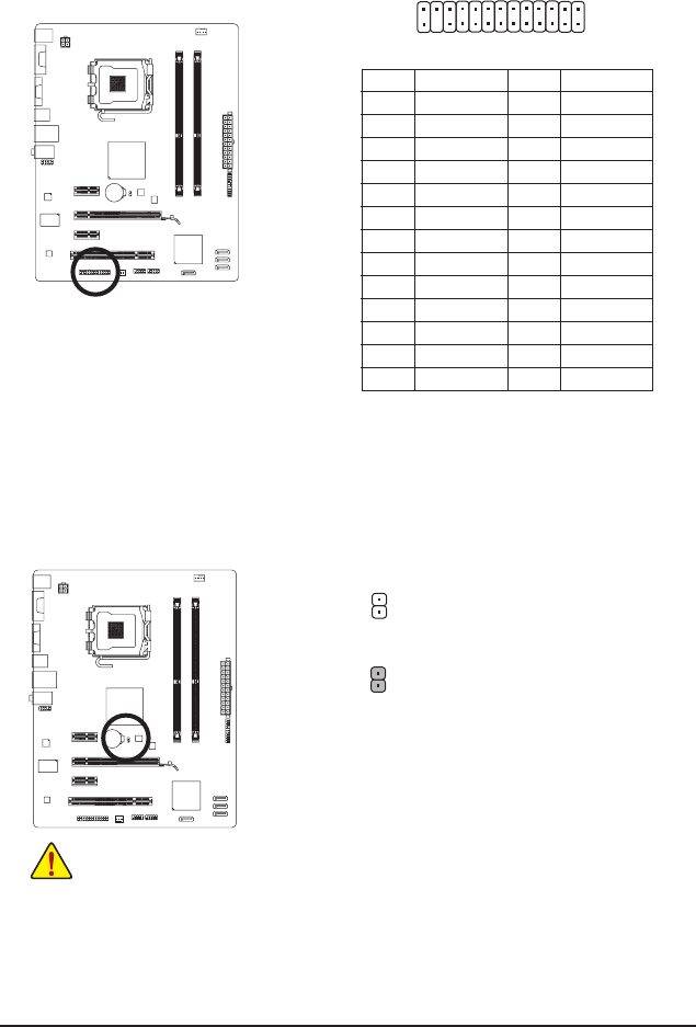
9) LPT (Parallel Port Header)
The LPT header can provide one parallel port via an optional LPT port cable. For purchasing the optional
LPT port cable, please contact the local dealer.
Pin No. Denition
14 GND
15 PD6
16 GND
17 PD7
18 GND
19 ACK-
20 GND
21 BUSY
22 GND
23 PE
24 No Pin
25 SLCT
26 GND
Pin No. Denition
1 STB-
2 AFD-
3 PD0
4 ERR-
5 PD1
6 INIT-
7 PD2
8 SLIN-
9 PD3
10 GND
11 PD4
12 GND
13 PD5
24
25
2
1
DEBUG
PORT
G.QBOFM
10) CLR_CMOS (Clearing CMOS Jumper)
Use this jumper to clear the CMOS values (e.g. date information and BIOS congurations) and reset
the CMOS values to factory defaults. To clear the CMOS values, place a jumper cap on the two pins to
temporarily short the two pins or use a metal object like a screwdriver to touch the two pins for a few
seconds.
Open: Normal
Short: Clear CMOS Values
• Always turn off your computer and unplug the power cord from the power outlet before clear-
ing the CMOS values.
• After clearing the CMOS values and before turning on your computer, be sure to remove the
jumper cap from the jumper. Failure to do so may cause damage to the motherboard.
• After system restart, go to BIOS Setup to load factory defaults (select Load Optimized
Defaults) or manually congure the BIOS settings (refer to Chapter 2, "BIOS Setup," for BIOS
congurations).