
User`s manual

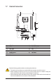
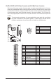
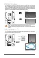

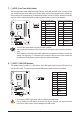

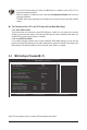
Table Of Contents
- GA-G41MT-S2 Motherboard Layout
- Chapter 1 Hardware Installation
- Chapter 2 BIOS Setup
- 2-1 Startup Screen
- 2-2 The Main Menu
- 2-3 MB Intelligent Tweaker(M.I.T.)
- 2-4 Standard CMOS Features
- 2-5 Advanced BIOS Features
- 2-6 Advanced Chipset Features
- 2-7 Integrated Peripherals
- 2-8 Power Management Setup
- 2-9 PnP/PCI Configurations
- 2-10 PC Health Status
- 2-11 Load Fail-Safe Defaults
- 2-12 Load Optimized Defaults
- 2-13 Set Supervisor/User Password
- 2-14 Save & Exit Setup
- 2-15 Exit Without Saving
- Chapter 3 Drivers Installation
- Regulatory Statements
Hardware Installation - 14 -
3/4) CPU_FAN/SYS_FAN (Fan Headers)
The motherboard has a 4-pin CPU fan header (CPU_FAN) and a 3-pin (SYS_FAN) system fan header.
Most fan headers possess a foolproof insertion design. When connecting a fan cable, be sure to connect
it in the correct orientation (the black connector wire is the ground wire). The motherboard supports CPU
fan speed control, which requires the use of a CPU fan with fan speed control design. For optimum heat
dissipation, it is recommended that a system fan be installed inside the chassis.
• Be sure to connect fan cables to the fan headers to prevent your CPU and system from over-
heating. Overheating may result in damage to the CPU or the system may hang.
• These fan headers are not conguration jumper blocks. Do not place a jumper cap on the
headers.
CPU_FAN:
Pin No. Denition
1 GND
2 +12V
3 Sense
4 Speed Control
SYS_FAN:
Pin No. Denition
1 GND
2 +12V
3 Sense
CPU_FAN
DEBUG
PORT
G.QBOFM
SYS_FAN
1
1
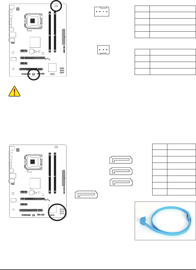
5) SATA2_0/1/2/3 (SATA 3Gb/s Connectors)
The SATA connectors conform to SATA 3Gb/s standard and are compatible with SATA 1.5Gb/s standard.
Each SATA connector supports a single SATA device.
Pin No. Denition
1 GND
2 TXP
3 TXN
4 GND
5 RXN
6 RXP
7 GND
SATA2_0
SATA2_1
SATA2_2
SATA2_3
DEBUG
PORT
G.QBOFM
DEBUG
PORT
G.QBOFM
DEBUG
PORT
G.QBOFM
7
7
7
1
1
1
7
DEBUG
PORT
G.QBOFM
1
Please connect the L-shaped end of
the SATA cable to your SATA hard
drive.