GA-G41MT-S2 LGA775 socket motherboard for Intel® Core™ processor family/ Intel® Pentium® processor family/Intel® Celeron® processor family User's Manual Rev.
Motherboard GA-G41MT-S2 Oct. 1, 2010 GA-G41MT-S2 Motherboard Oct.
Copyright © 2010 GIGA-BYTE TECHNOLOGY CO., LTD. All rights reserved. The trademarks mentioned in this manual are legally registered to their respective owners. Disclaimer Information in this manual is protected by copyright laws and is the property of GIGABYTE. Changes to the specifications and features in this manual may be made by GIGABYTE without prior notice.
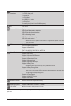
Table of Contents GA-G41MT-S2 Motherboard Layout.................................................................................5 Chapter 1 Hardware Installation......................................................................................6 1-1 1-2 1-3 Installation Precautions..................................................................................... 6 Product Specifications.......................................................................................
GA-G41MT-S2 Motherboard Layout CPU_FAN KB_MS ATX_12V COMA LGA775 VGA ATX R_USB BATTERY CLR_CMOS PCIEX1_1 Atheros AR8151 B_BIOS M_BIOS F_PANEL Intel® G41 F_AUDIO DDR3_2 AUDIO DDR3_1 GA-G41MT-S2 USB_LAN PCIEX16 iTE IT8718 CODEC PCIEX1_2 PCI Intel® ICH7 LPT SYS_FAN F_USB2 F_USB1 SATA2_3 SATA2_2 SATA2_1 SATA2_0 Box Contents GA-G41MT-S2 motherboard Two SATA cables I/O Shield Motherboard driver disk User's Manual The box contents above are for reference only and the actual items
Chapter 1 1-1 Hardware Installation Installation Precautions The motherboard contains numerous delicate electronic circuits and components which can become damaged as a result of electrostatic discharge (ESD). Prior to installation, carefully read the user's manual and follow these procedures: • Prior to installation, do not remove or break motherboard S/N (Serial Number) sticker or warranty sticker provided by your dealer. These stickers are required for warranty validation.
1-2 Product Specifications CPU w w Front Side Bus w Chipset w w Memory w w Onboard Graphics Audio Support for an Intel® Core™ 2 Extreme processor/ Intel® Core™ 2 Quad processor/Intel® Core™ 2 Duo processor/ Intel® Pentium® processor/Intel® Celeron® processor in the LGA775 package (Go to GIGABYTE's website for the latest CPU support list.
Back Panel Connectors w w w w w w w 1 x PS/2 keyboard port 1 x PS/2 mouse port 1 x serial port 1 x D-Sub port 4 x USB 2.0/1.
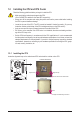
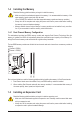
1-3 Installing the CPU and CPU Cooler Read the following guidelines before you begin to install the CPU: • Make sure that the motherboard supports the CPU. (Go to GIGABYTE's website for the latest CPU support list.) • Always turn off the computer and unplug the power cord from the power outlet before installing the CPU to prevent hardware damage. • Locate the pin one of the CPU. The CPU cannot be inserted if oriented incorrectly.
1-4 Installing the Memory Read the following guidelines before you begin to install the memory: • Make sure that the motherboard supports the memory. It is recommended that memory of the same capacity, brand, speed, and chips be used. (Go to GIGABYTE's website for the latest supported memory speeds and memory modules.) • Always turn off the computer and unplug the power cord from the power outlet before installing the memory to prevent hardware damage. • Memory modules have a foolproof design.
1-6 Back Panel Connectors PS/2 Keyboard and PS/2 Mouse Port Use the upper port (green) to connect a PS/2 mouse and the lower port (purple) to connect a PS/2 keyboard. Serial Port Use the serial port to connect devices such as a mouse, modem or other peripherals. D-Sub Port The D-Sub port supports a 15-pin D-Sub connector. Connect a monitor that supports D-Sub connection to this port. USB 2.0/1.1 Port The USB port supports the USB 2.0/1.1 specification.
1-7 Internal Connectors 1 3 2 7 6 11 10 9 1) 2) 3) 4) 5) 6) ATX_12V ATX CPU_FAN SYS_FAN SATA2_0/1/2/3 F_PANEL 4 8 5 7) 8) 9) 10) 11) F_AUDIO F_USB1/F_USB2 LPT CLR_CMOS BATTERY Read the following guidelines before connecting external devices: • First make sure your devices are compliant with the connectors you wish to connect. • Before installing the devices, be sure to turn off the devices and your computer. Unplug the power cord from the power outlet to prevent damage to the devices.
1/2) ATX_12V/ATX (2x2 12V Power Connector and 2x12 Main Power Connector) With the use of the power connector, the power supply can supply enough stable power to all the components on the motherboard. Before connecting the power connector, first make sure the power supply is turned off and all devices are properly installed. The power connector possesses a foolproof design. Connect the power supply cable to the power connector in the correct orientation.
3/4) CPU_FAN/SYS_FAN (Fan Headers) The motherboard has a 4-pin CPU fan header (CPU_FAN) and a 3-pin (SYS_FAN) system fan header. Most fan headers possess a foolproof insertion design. When connecting a fan cable, be sure to connect it in the correct orientation (the black connector wire is the ground wire). The motherboard supports CPU fan speed control, which requires the use of a CPU fan with fan speed control design.
6) F_PANEL (Front Panel Header) Connect the power switch, reset switch, speaker and system status indicator on the chassis front panel to this header according to the pin assignments below. Note the positive and negative pins before connecting the cables. SPEAK- 20 19 Speaker CI+ CIRES+ RESHDHD+ G.
7) F_AUDIO (Front Panel Audio Header) The front panel audio header supports Intel High Definition audio (HD) and AC'97 audio. You may connect your chassis front panel audio module to this header. Make sure the wire assignments of the module connector match the pin assignments of the motherboard header. Incorrect connection between the module connector and the motherboard header will make the device unable to work or even damage it. 2 10 1 9 For HD Front Panel Audio: Pin No.
9) LPT (Parallel Port Header) The LPT header can provide one parallel port via an optional LPT port cable. For purchasing the optional LPT port cable, please contact the local dealer. Pin No. 1 2 3 4 5 6 7 8 9 10 11 12 13 25 1 24 2 Definition STBAFDPD0 ERRPD1 INITPD2 SLINPD3 GND PD4 GND PD5 Pin No. 14 15 16 17 18 19 20 21 22 23 24 25 26 Definition GND PD6 GND PD7 GND ACKGND BUSY GND PE No Pin SLCT GND 10) CLR_CMOS (Clearing CMOS Jumper) Use this jumper to clear the CMOS values (e.g.
11) BATTERY The battery provides power to keep the values (such as BIOS configurations, date, and time information) in the CMOS when the computer is turned off. Replace the battery when the battery voltage drops to a low level, or the CMOS values may not be accurate or may be lost. You may clear the CMOS values by removing the battery: 1. Turn off your computer and unplug the power cord. 2. Gently remove the battery from the battery holder and wait for one minute.
Chapter 2 BIOS Setup To access the BIOS Setup program, press the key during the POST when the power is turned on. To see more advanced BIOS Setup menu options, you can press + in the main menu of the BIOS Setup program. To upgrade the BIOS, use either the GIGABYTE Q-Flash or @BIOS utility. • Q-Flash allows the user to quickly and easily upgrade or back up BIOS without entering the operating system.
• If you do not find the settings you want in the Main Menu or a submenu, press + to access more advanced options. • When the system is not stable as usual, select the Load Optimized Defaults item to set your system to its defaults. • The BIOS Setup menus described in this chapter are for reference only and may differ by BIOS version.
CMOS Setup Utility-Copyright (C) 1984-2010 Award Software MB Intelligent Tweaker(M.I.T.) x x x x CAS Latency Time tRCD tRP tRAS >>>>> Advanced Timing Control } Advanced Timing Control 9 9 9 24 Item Help Menu Level Auto Auto Auto Auto [Press Enter] ******** Mother Board Voltage Control ******** Voltage Types Normal Current ---------------------------------------------------------------------------->>> CPU CPU Vcore 1.17500V [Auto] CPU Termination 1.
CPU Host Frequency (Mhz) Allows you to manually set the CPU host frequency. The adjustable range is from 100 MHz to 1200 MHz. This item is configurable only if the CPU Host Clock Control option is enabled. Important: It is highly recommended that the CPU frequency be set in accordance with the CPU specifications. PCI Express Frequency (Mhz) Allows you to manually set the PCIe clock frequency. The adjustable range is from 90 MHz to 150 MHz. Auto sets the PCIe clock frequency to standard 100 MHz.
CMOS Setup Utility-Copyright (C) 1984-2010 Award Software Advanced Timing Control x x x x x x tRRD tWTR tWR tRFC tRTP Command Rate (CMD) Item Help Menu Level Auto Auto Auto Auto Auto Auto >>>>> Channel A } Channel A Timing Settings } Channel A Driving Settings [Press Enter] [Press Enter] >>>>> Channel B } Channel B Timing Settings } Channel B Driving Settings [Press Enter] [Press Enter] Enter: Select : Move F5: Previous Values +/-/PU/PD: Value F10: Save F6: F
tRD Phase0 Adjustment Options are: Auto (default), 0-Normal, 1-Advanced. tRD Phase1 Adjustment Options are: Auto (default), 0-Normal, 1-Advanced. tRD Phase2 Adjustment Options are: Auto (default), 0-Normal, 1-Advanced. tRD Phase3 Adjustment Options are: Auto (default), 0-Normal, 1-Advanced. Trd2rd(Different Rank) Options are: Auto (default), 1~15. Twr2wr(Different Rank) Options are: Auto (default), 1~15. Twr2rd(Different Rank) Options are: Auto (default), 1~15.
Driving Strength Profile Options are: Auto (default). Data Driving Pull-Up Level Options are: Auto (default), +8~-7. Cmd Driving Pull-Up Level Options are: Auto (default), +8~-7. Ctrl Driving Pull-Up Level Options are: Auto (default), +8~-7. Clk Driving Pull-Up Level Options are: Auto (default), +8~-7. Data Driving Pull-Down Lev Options are: Auto (default), +8~-7. Cmd Driving Pull-Down Lev Options are: Auto (default), +8~-7. Ctrl Driving Pull-Down Lev Options are: Auto (default), +8~-7.
2-4 Standard CMOS Features CMOS Setup Utility-Copyright (C) 1984-2010 Award Software Standard CMOS Features } } } } Date (mm:dd:yy) Time (hh:mm:ss) The, Sep 16 2010 22:31:24 IDE Channel 0 Master IDE Channel 0 Slave IDE Channel 1 Master IDE Channel 1 Slave [None] [None] [None] [None] Halt On [All, But Keyboard] Base Memory Extended Memory Total Memory 640K 988M 990M Enter: Select : Move F5: Previous Values +/-/PU/PD: Value F10: Save F6: Fail-Safe Defaults
2-5 Advanced BIOS Features CMOS Setup Utility-Copyright (C) 1984-2010 Award Software Advanced BIOS Features } Hard Disk Boot Priority Quick Boot First Boot Device Second Boot Device Third Boot Device Password Check HDD S.M.A.R.T. Capability CPU Multi-Threading (Note) Limit CPUID Max.
Limit CPUID Max. to 3 (Note) Allows you to determine whether to limit CPUID maximum value. Set this item to Disabled for Windows XP operating system; set this item to Enabled for legacy operating system such as Windows NT4.0. (Default: Disabled) No-Execute Memory Protect (Note) Enables or disables Intel Execute Disable Bit function. This function may enhance protection for the computer, reducing exposure to viruses and malicious buffer overflow attacks when working with its supporting software and system.
2-6 Advanced Chipset Features CMOS Setup Utility-Copyright (C) 1984-2010 Award Software Advanced Chipset Features ** VGA Setting ** Onboard VGA Init Display First PAVP Mode PAVP Lite Mode x Paranoid PAVP Mode Enter: Select : Move F5: Previous Values [Enable If No Ext PEG] [PCI] [PAVP Lite Mode] [32MB] (32+96)128MB +/-/PU/PD: Value F10: Save F6: Fail-Safe Defaults Item Help Menu Level ESC: Exit F1: General Help F7: Optimized Defaults Onboard VGA Enables or disables the onb
2-7 Integrated Peripherals CMOS Setup Utility-Copyright (C) 1984-2010 Award Software Integrated Peripherals Azalia Codec Onboard H/W LAN } SMART LAN Onboard LAN Boot ROM Onboard Serial Port 1 Onboard Parallel Port Parallel Port Mode USB 1.0 Controller USB 2.
Parallel Port Mode Selects an operating mode for the onboard parallel (LPT) port. Options are: SPP (Standard Parallel Port) (default), EPP (Enhanced Parallel Port), ECP (Extended Capabilities Port), ECP+EPP. USB 1.0 Controller Enables or disables the integrated USB 1.0 controller. (Default: Enabled) Disabled will turn off all of the USB functionalities below. USB 2.0 Controller Enables or disables the integrated USB 2.0 controller.
Soft-Off by PWR-BTTN Configures the way to turn off the computer in MS-DOS mode using the power button. Instant-Off Press the power button and then the system will be turned off instantly. (Default) Delay 4 Sec. Press and hold the power button for 4 seconds to turn off the system. If the power button is pressed for less than 4 seconds, the system will enter suspend mode. PME Event Wake Up Allows the system to be awakened from an ACPI sleep state by a wake-up signal from a PCI or PCIe device.
AC Back Function Determines the state of the system after the return of power from an AC power loss. Soft-Off The system stays off upon the return of the AC power. (Default) Full-On The system is turned on upon the return of the AC power. Memory The system returns to its last known awake state upon the return of the AC power. ErP Support Determines whether to let the system consume less than 1W power in S5 (shutdown) state.
Current Voltage(V) Vcore/DDR15V/+3.3V/+12V Displays the current system voltages. Current CPU Temperature Displays current CPU temperature. Current CPU/SYSTEM FAN Speed (RPM) Displays current CPU/system fan speed. CPU Warning Temperature Sets the warning threshold for CPU temperature. When CPU temperature exceeds the threshold, BIOS will emit warning sound. Options are: Disabled (default), 60oC/140oF, 70oC/158oF, 80oC/176oF, 90oC/194oF.
2-12 Load Optimized Defaults CMOS Setup Utility-Copyright (C) 1984-2010 Award Software MB Intelligent Tweaker(M.I.T.
2-14 Save & Exit Setup CMOS Setup Utility-Copyright (C) 1984-2010 Award Software MB Intelligent Tweaker(M.I.T.
Chapter 3 Drivers Installation • Before installing the drivers, first install the operating system. • After installing the operating system, insert the motherboard driver disk into your optical drive. The driver Autorun screen is automatically displayed which looks like that shown in the screen shot below. (If the driver Autorun screen does not appear automatically, go to My Computer, double-click the optical drive and execute the Run.exe program.
Regulatory Statements Regulatory Notices This document must not be copied without our written permission, and the contents there of must not be imparted to a third party nor be used for any unauthorized purpose. Contravention will be prosecuted. We believe that the information contained herein was accurate in all respects at the time of printing. GIGABYTE cannot, however, assume any responsibility for errors or omissions in this text.
Finally, we suggest that you practice other environmentally friendly actions by understanding and using the energy-saving features of this product (where applicable), recycling the inner and outer packaging (including shipping containers) this product was delivered in, and by disposing of or recycling used batteries properly.
Contact Us GIGA-BYTE TECHNOLOGY CO., LTD. Address: No.6, Bau Chiang Road, Hsin-Tien, Taipei 231, Taiwan TEL: +886-2-8912-4000, FAX: +886-2-8912-4003 Tech. and Non-Tech. Support (Sales/Marketing) : http://ggts.gigabyte.com.tw WEB address (English): http://www.gigabyte.com WEB address (Chinese): http://www.gigabyte.tw You may go to the GIGABYTE website, select your language in the language list on the top right corner of the website.