GA-A75M-DS2 User's Manual Rev.
Motherboard GA-A75M-DS2 Mar. 30, 2012 GA-A75M-DS2 Motherboard Mar.
Copyright © 2012 GIGA-BYTE TECHNOLOGY CO., LTD. All rights reserved. The trademarks mentioned in this manual are legally registered to their respective owners. Disclaimer Information in this manual is protected by copyright laws and is the property of GIGABYTE. Changes to the specifications and features in this manual may be made by GIGABYTE without prior notice.
Table of Contents GA-A75M-DS2 Motherboard Layout................................................................................5 GA-A75M-DS2 Motherboard Block Diagram...................................................................6 Chapter 1 Hardware Installation......................................................................................7 1-1 1-2 1-3 1-4 1-5 1-6 1-7 1-8 Installation Precautions....................................................................................
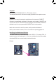
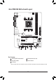
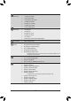
GA-A75M-DS2 Motherboard Layout CPU_FAN KB_MS_USB ATX_12V VGA Socket FM1 DVI ATX R_USB30 Realtek/Atheros GbE LAN BAT GA-A75M-DS2 DDR3_1 AUDIO DDR3_2 USB_LAN PCIEX16 3 2 PCIEX1 iTE Super I/O SATA3 M_BIOS AMD A75 B_BIOS CODEC SATA3 PCI 1 0 CLR_CMOS F_AUDIO SYS_FAN SPDIF_O F_USB1 F_USB30 F_PANEL F_USB2 Box Contents GA-A75M-DS2 motherboard Two SATA cables I/O Shield Motherboard driver disk User's Manual * The box contents above are for reference only and the actual items shall depen
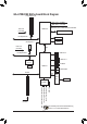
GA-A75M-DS2 Motherboard Block Diagram 1 PCI Express x16 APU CLK+/- (100 MHz) DISP CLK+/- (100 MHz) PCIe CLK (100 MHz) DDR3 2400 (O.C.)/1866/1600/1333/1066 MHz AMD APU Dual Channel Memory x16 PCI Express Bus DVI-D D-Sub 1 PCI Express x1 PCIe CLK (100 MHz) UMI x1 PCI Express Bus 4 USB 3.0/2.0 x1 8 USB 2.0/1.
Chapter 1 1-1 Hardware Installation Installation Precautions The motherboard contains numerous delicate electronic circuits and components which can become damaged as a result of electrostatic discharge (ESD). Prior to installation, carefully read the user's manual and follow these procedures: •• Prior to installation, make sure the chassis is suitable for the motherboard. •• Prior to installation, do not remove or break motherboard S/N (Serial Number) sticker or warranty sticker provided by your dealer.
1-2 Product Specifications APU FM1 Socket: - AMD A series processors/AMD E2 series processors - AMD Athlon™ II processors/Sempron™ processors (Go to GIGABYTE's website for the latest APU support list.) Chipset AMD A75 Memory 2 x 1.5V DDR3 DIMM sockets supporting up to 32 GB of system memory Onboard Graphics * Due to Windows 32-bit operating system limitation, when more than 4 GB of physical memory is installed, the actual memory size displayed will be less than 4 GB.
Internal Connectors Back Panel Connectors 1 x APU fan header 1 x system fan header 1 x front panel header 1 x front panel audio header 1 x S/PDIF Out header 2 x USB 2.0/1.1 headers 1 x USB 3.0/2.0 header 1 x Clear CMOS jumper 1 x PS/2 keyboard/mouse port 1 x D-Sub port 1 x DVI-D port 4 x USB 2.0/1.1 ports 2 x USB 3.0/2.
Bundled Software Operating System Form Factor Norton Internet Security (OEM version) Support for Microsoft® Windows 7/Vista/XP Micro ATX Form Factor; 22.5cm x 17.4cm *G IGABYTE reserves the right to make any changes to the product specifications and product-related information without prior notice. 1-3 Installing the APU Read the following guidelines before you begin to install the APU: • Make sure that the motherboard supports the APU.
1-4 Installing the Memory Read the following guidelines before you begin to install the memory: •• Make sure that the motherboard supports the memory. It is recommended that memory of the same capacity, brand, speed, and chips be used. (Go to GIGABYTE's website for the latest supported memory speeds and memory modules.) •• Always turn off the computer and unplug the power cord from the power outlet before installing the memory to prevent hardware damage. •• Memory modules have a foolproof design.
1-6 Setup of the AMD Dual Graphics Configuration Combining the onboard GPU with a discrete graphics card, AMD's Dual Graphics technology can provide significantly advanced display performance for AMD platform. Read the following instructions on configuring a Dual Graphics system. A.
1-7 Back Panel Connectors USB 2.0/1.1 Port The USB port supports the USB 2.0/1.1 specification. Use this port for USB devices such as a USB keyboard/mouse, USB printer, USB flash drive and etc. PS/2 Keyboard and PS/2 Mouse Port Use this port to connect a PS/2 mouse or keyboard. D-Sub Port (Note 1) The D-Sub port supports a 15-pin D-Sub connector. Connect a monitor that supports D-Sub connection to this port.
1-8 Internal Connectors 1 3 2 12 5 5 7 8 4 1) 2) 3) 4) 5) 6) ATX_12V ATX CPU_FAN SYS_FAN SATA3 0/1/2/3 F_PANEL 9 6 11 10 9 7) 8) 9) 10) 11) 12) F_AUDIO SPDIF_O F_USB1/F_USB2 F_USB30 CLR_CMOS BAT Read the following guidelines before connecting external devices: •• First make sure your devices are compliant with the connectors you wish to connect. •• Before installing the devices, be sure to turn off the devices and your computer.
1/2) ATX_12V/ATX (2x2 12V Power Connector and 2x12 Main Power Connector) With the use of the power connector, the power supply can supply enough stable power to all the components on the motherboard. Before connecting the power connector, first make sure the power supply is turned off and all devices are properly installed. The power connector possesses a foolproof design. Connect the power supply cable to the power connector in the correct orientation.
3/4) CPU_FAN/SYS_FAN (Fan Headers) The motherboard has a 4-pin CPU fan header (CPU_FAN) and a 4-pin system fan header (SYS_FAN). Most fan headers possess a foolproof insertion design. When connecting a fan cable, be sure to connect it in the correct orientation (the black connector wire is the ground wire). The motherboard supports APU fan speed control, which requires the use of a APU fan with fan speed control design.
6) F_PANEL (Front Panel Header) Connect the power switch, reset switch, speaker, and system status indicator on the chassis to this header according to the pin assignments below. Note the positive and negative pins before connecting the cables. Power Switch Hard Drive Reset Activity LED Switch SPEAK- Power LED Chassis Intrusion Header • MSG/PWR (Message/Power/Sleep LED): Connects to the power status indicator on the chassis front panel.
7) F_AUDIO (Front Panel Audio Header) The front panel audio header supports Intel High Definition audio (HD) and AC'97 audio. You may connect your chassis front panel audio module to this header. Make sure the wire assignments of the module connector match the pin assignments of the motherboard header. Incorrect connection between the module connector and the motherboard header will make the device unable to work or even damage it. 9 10 For HD Front Panel Audio: Pin No.
9) F_USB1/F_USB2 (USB 2.0/1.1 Headers) The headers conform to USB 2.0/1.1 specification. Each USB header can provide two USB ports via an optional USB bracket. For purchasing the optional USB bracket, please contact the local dealer. 9 10 1 2 Pin No. 1 2 3 4 5 6 7 8 9 10 Definition Power (5V) Power (5V) USB DXUSB DYUSB DX+ USB DY+ GND GND No Pin NC 10) F_USB30 (USB 3.0/2.0 Header) The header conforms to USB 3.0/2.0 specification and can provide two USB ports. For purchasing the optional 3.
11) CLR_CMOS (Clear CMOS Jumper) Use this jumper to clear the CMOS values (e.g. date information and BIOS configurations) and reset the CMOS values to factory defaults. To clear the CMOS values, place a jumper cap on the two pins to temporarily short the two pins or use a metal object like a screwdriver to touch the two pins for a few seconds. Open: Normal Short: Clear CMOS Values •• Always turn off your computer and unplug the power cord from the power outlet before clearing the CMOS values.
Chapter 2 BIOS Setup To access the BIOS Setup program, press the key during the POST when the power is turned on. To see more advanced BIOS Setup menu options, you can press + in the main menu of the BIOS Setup program. To upgrade the BIOS, use either the GIGABYTE Q-Flash or @BIOS utility. •• Q-Flash allows the user to quickly and easily upgrade or back up BIOS without entering the operating system.
2-2 The Main Menu Once you enter the BIOS Setup program, the Main Menu (as shown below) appears on the screen. Use arrow keys to move among the items and press to accept or enter a sub-menu. (Sample BIOS Version: F2a) CMOS Setup Utility-Copyright (C) 1984-2012 Award Software MB Intelligent Tweaker(M.I.T.
2-3 MB Intelligent Tweaker(M.I.T.) CMOS Setup Utility-Copyright (C) 1984-2012 Award Software MB Intelligent Tweaker(M.I.T.) } IGX Configuration CPU Clock Ratio CPU NB Clock Divisor Core Performance Boost (Note) CPB Ratio (Note) CPU Host Clock Control x CPU Host Clock DRAM E.O.C.
Surround View Enables or disables the Surround View function. This option is configurable only if Init Display First under Advanced BIOS Features is set to PEG and an AMD/ATI graphics card is installed. (Default: Disabled) VGA Core Clock control Allows you to determine whether to manually set the VGA Core clock. (Default: Auto) VGA Core Clock(MHz) Allows you to manually set the VGA Core clock. The adjustable range is from 300 MHz to 2000 MHz.
DRAM Configuration CMOS Setup Utility-Copyright (C) 1984-2012 Award Software DRAM Configuration x x x x x x x x x x x x x DDR3 Timing Items 1T/2T Command Timing CAS# latency RAS to CAS R/W Delay Row Precharge Time Minimum RAS Active Time TwTr Command Delay Trfc0 for DIMM2 Trfc1 for DIMM1 Write Recovery Time Precharge Time Row Cycle Time RAS to RAS Delay Four Bank Activate Window **DCTs Drive Strength** ProcOdt(ohms) DQS Drive Strength Data Drive Strength MEMCLK Drive Strength Ente
Minimum RAS Active Time Options are: Auto (default), 15T~36T. TwTr Command Delay Options are: Auto (default), 4T~8T. Trfc0 for DIMM2 Options are: Auto (default), 90ns, 110ns, 160ns, 300ns, 350ns. Trfc1 for DIMM1 Options are: Auto (default), 90ns, 110ns, 160ns, 300ns, 350ns. Write Recovery Time Options are: Auto (default), 5T~8T, 10T~16T. Precharge Time Options are: Auto (default), 4T~8T. Row Cycle Time Options are: Auto (default), 20T~54T. RAS to RAS Delay Options are: Auto (default), 4T~8T.
CKE Setup Time Options are: Auto (default), 1/2T, 1T. CKE Fine Delay Options are: Auto (default), 0/64~31/64. && Bank Interleaving Enables or disables memory bank interleaving. Enabled allows the system to simultaneously access different banks of the memory to increase memory performance and stability. (Default: Enabled) ******** System Voltage Optimized ******** && System Voltage Control Determines whether to manually set the system voltages.
2-4 Standard CMOS Features CMOS Setup Utility-Copyright (C) 1984-2012 Award Software Standard CMOS Features } } } } Date (mm:dd:yy) Time (hh:mm:ss) Wed, Jul 20 2012 22:31:24 IDE Channel 0 Master IDE Channel 0 Slave IDE Channel 1 Master IDE Channel 1 Slave [None] [None] [None] [None] Halt On [All, But Keyboard] Base Memory Extended Memory Enter: Select : Move F5: Previous Values Item Help Menu Level 640K 941M +/-/PU/PD: Value F10: Save F6: Fail-Safe Defaults ESC: Exit F1:
2-5 Advanced BIOS Features CMOS Setup Utility-Copyright (C) 1984-2012 Award Software Advanced BIOS Features } IGX Configuration Load Line Control AMD C6 Support Virtualization AMD K8 Cool&Quiet control C-state Pmin } Hard Disk Boot Priority EFI CD/DVD Boot Option First Boot Device Second Boot Device Third Boot Device Password Check HDD S.M.A.R.T.
EFI CD/DVD Boot Option Set this item to EFI if you want to install the operating system to a hard drive larger than 2.2 TB. Make sure the operating system to be installed supports booting from a GPT partition, such as Windows 7 64bit and Windows Server 2003 64-bit. Auto lets the BIOS automatically configure this setting depending on the hard drive you install. (Default: Auto) First/Second/Third Boot Device Specifies the boot order from the available devices.
OnChip SATA Controller Enables or disables the integrated SATA controllers. (Default: Enabled) OnChip SATA Type Configures the operating mode of the SATA connectors. Native IDE Allows the SATA controller to operate in Native IDE mode. (Default) Enable Native IDE mode if you wish to install operating systems that support Native mode. RAID Enables RAID for the SATA controller. AHCI Configures the SATA controllers to AHCI mode.
Onboard Audio Function Enables or disables the onboard audio function. (Default: Enabled) If you wish to install a 3rd party add-in audio card instead of using the onboard audio, set this item to Disabled. Onchip USB 3.0 Controller Enables or disables the onboard USB 3.0 controller. (Default: Enabled) USB Controllers Enables or disables the integrated USB controllers. (Default: Enabled) Disabled will turn off all of the USB functionalities below.
PME Event Wake Up Allows the system to be awakened from an ACPI sleep state by a wake-up signal from a PCI or PCIe device. Note: To use this function, you need an ATX power supply providing at least 1A on the +5VSB lead. (Default: Enabled) HPET Support (Note) Enables or disables High Precision Event Timer (HPET) for Windows 7/Vista operating system. (Default: Enabled) Power On By Mouse Allows the system to be turned on by a PS/2 mouse wake-up event.
2-8 PC Health Status CMOS Setup Utility-Copyright (C) 1984-2012 Award Software PC Health Status Hardware Thermal Control Reset Case Open Status Case Opened Vcore DDR15V +12V VCC3 Current System Temperature Current CPU Temperature Current CPU FAN Speed Current SYSTEM FAN Speed CPU Warning Temperature CPU FAN Fail Warning SYSTEM FAN Fail Warning CPU Smart FAN Control System Smart FAN Control Enter: Select : Move F5: Previous Values [Enabled] [Disabled] No 1.364V 1.
System Smart FAN Control Enables or disables the system fan speed control function. Enabled allows the system fan to run at different speed according to the system temperature. If disabled, system fan runs at full speed. (Default: Enabled) 2-9 Load Fail-Safe Defaults CMOS Setup Utility-Copyright (C) 1984-2012 Award Software MB Intelligent Tweaker(M.I.T.
2-11 Set Supervisor/User Password CMOS Setup Utility-Copyright (C) 1984-2012 Award Software MB Intelligent Tweaker(M.I.T.
2-13 Exit Without Saving CMOS Setup Utility-Copyright (C) 1984-2012 Award Software MB Intelligent Tweaker(M.I.T.
Chapter 4 4-1 Appendix Configuring SATA Hard Drive(s) Before you begin Please prepare: • At least two SATA hard drives (to ensure optimal performance, it is recommended that you use two hard drives with identical model and capacity). If you do not want to create RAID, you may prepare only one hard drive. • Windows 7/Vista/XP setup disk. • Motherboard driver disk.
5. Press + keys to save the information. The message in Figure 1 will appear. Press + to input the array name. If you do not input the array name, the default array name will be used. Please press Ctrl-Y key to input the LD Name or press any key to exit. If you do not input any LD name, the default LD name will be used. Figure 1 6. When the next message appears, press + to clear the MBR or press other keys to ignore this option.
4-2 Regulatory Statements Regulatory Notices This document must not be copied without our written permission, and the contents there of must not be imparted to a third party nor be used for any unauthorized purpose. Contravention will be prosecuted. We believe that the information contained herein was accurate in all respects at the time of printing. GIGABYTE cannot, however, assume any responsibility for errors or omissions in this text.
- 41 -
- 42 -
- 43 -
Contact Us GIGA-BYTE TECHNOLOGY CO., LTD. Address: No.6, Bao Chiang Road, Hsin-Tien Dist., New Taipei City 231, Taiwan TEL: +886-2-8912-4000, FAX: +886-2-8912-4003 Tech. and Non-Tech. Support (Sales/Marketing) : http://ggts.gigabyte.com.tw WEB address (English): http://www.gigabyte.com WEB address (Chinese): http://www.gigabyte.tw You may go to the GIGABYTE website, select your language in the language list on the top right corner of the website.