GA-78LMT-USB3 User's Manual Rev.
Motherboard GA-78LMT-USB3 Jul. 27, 2012 Motherboard GA-78LMT-USB3 Jul.
Copyright © 2012 GIGA-BYTE TECHNOLOGY CO., LTD. All rights reserved. The trademarks mentioned in this manual are legally registered to their respective owners. Disclaimer Information in this manual is protected by copyright laws and is the property of GIGABYTE. &KDQJHV WR WKH VSHFL¿FDWLRQV DQG IHDWXUHV LQ WKLV PDQXDO PD\ EH PDGH E\ *,*$%<7( ZLWKRXW prior notice.
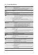
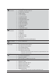
Table of Contents GA-78LMT-USB3 Motherboard Layout ...........................................................................5 GA-78LMT-USB3 Motherboard Block Diagram ..............................................................6 Chapter 1 Hardware Installation .....................................................................................7 1-1 Installation Precautions ................................................................................... 7 3URGXFW 6SHFL¿FDWLRQV ................
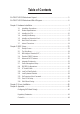
GA-78LMT-USB3 Motherboard Layout CPU_FAN KB_MS_USB SYS_FAN DVI VGA ATX_12V AM3+ HDMI ATX IDE R_USB30 SATA2 Etron EJ168 USB_LAN 5 4 AUDIO iTE Super I/O DDR3_1 B_BIOS PCIEX1 BAT CODEC DDR3_3 DDR3_4 PCIEX16 DDR3_2 AMD 760G Realtek GbE LAN AMD SB710 GA-78LMT-USB3 M_BIOS Etron EJ168 PCI SATA2 2 3 0 1 CLR_CMOS F_USB30 F_AUDIO SPDIF_O LPT COM F_USB2 F_USB1 F_PANEL Box Contents 5 5 5 5 GA-78LMT-USB3 motherboard Motherboard driver disk User's Manual I/O Shield 5 Two SATA cables 5
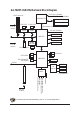
GA-78LMT-USB3 Motherboard Block Diagram CPU CLK+/- (200 MHz) 1 PCI Express x16 DDR3 1333+ (O.C.)/1066 MHz AM3+/AM3 CPU Dual Channel Memory 2 USB 3.0/2.0 2 USB 3.0/2.0 Hyper Transport 3.0 PCIe CLK (100 MHz) Etron EJ168 Etron EJ168 x1 x1 x1 x1 x16 GFX CLK (100 MHz) HDMI AMD 760G PCI Express Bus DVI-D Realtek GbE LAN PCIe CLK (100 MHz) 1 PCI Express x1 D-Sub RJ45 LAN 8 USB 2.0/1.
Chapter 1 1-1 Hardware Installation Installation Precautions The motherboard contains numerous delicate electronic circuits and components which can become damaged as a result of electrostatic discharge (ESD). Prior to installation, carefully read the user's manual and follow these procedures: Prior to installation, make sure the chassis is suitable for the motherboard. Prior to installation, do not remove or break motherboard S/N (Serial Number) sticker or warranty sticker provided by your dealer.
3URGXFW 6SHFLÀFDWLRQV CPU Hyper Transport Bus Chipset Memory AM3+ Socket: - AMD AM3+ processor - AMD AM3 Phenom™ II processor/ AMD Athlon™ II processor (Go to GIGABYTE's website for the latest CPU support list.
Internal Connectors 1 x 24-pin ATX main power connector 1 x 8-pin ATX 12V power connector 6 x SATA 3Gb/s connectors 1 x IDE connector 1 x CPU fan header 1 x system fan header 1 x front panel header 1 x front panel audio header 1 x S/PDIF Out header 1 x USB 3.0/2.0 header 2 x USB 2.0/1.1 headers 1 x serial port header 1 x parallel port 1 x Clear CMOS jumper 1 x PS/2 keyboard/mouse port 1 x D-Sub port 1 x DVI-D port 1 x HDMI port 2 x USB 3.0/2.0 ports 4 x USB 2.
Unique Features Bundled Software Operating System Support for Smart Recovery Support for Auto Green Support for ON/OFF Charge Support for Q-Share Form Factor Micro ATX Form Factor; 24.4cm x 24.4cm Norton Internet Security (OEM version) Support for Microsoft® Windows 7/Vista/XP * GIGABYTE reserves the right to make any changes to the product speci¿cations and product-related information without prior notice.
1-4 Installing the Memory Read the following guidelines before you begin to install the memory: Make sure that the motherboard supports the memory. It is recommended that memory of the same capacity, brand, speed, and chips be used. (Go to GIGABYTE's website for the latest supported memory speeds and memory modules.) Always turn off the computer and unplug the power cord from the power outlet before installing the memory to prevent hardware damage. Memory modules have a foolproof design.
1-6 Back Panel Connectors USB 2.0/1.1 Port 7KH 86% SRUW VXSSRUWV WKH 86% VSHFL¿FDWLRQ 8VH WKLV SRUW IRU 86% GHYLFHV VXFK DV D 86% NH\ERDUG PRXVH 86% SULQWHU 86% ÀDVK GULYH DQG HWF PS/2 Keyboard/Mouse Port Use this port to connect a PS/2 mouse or keyboard. D-Sub Port The D-Sub port supports a 15-pin D-Sub connector. Connect a monitor that supports D-Sub connection to this port.
$ 'XDO 'LVSOD\ &RQÀJXUDWLRQV This motherboard provides three video output ports: DVI-D, HDMI, and HDMI. The table below shows the VXSSRUWHG GXDO GLVSOD\ FRQ¿JXUDWLRQV Dual Display Combination Supported or Not D-Sub + DVI-D Yes D-Sub + HDMI Yes DVI-D + HDMI No B. Playback of Blu-ray™ 'LVFV In order to get better playback quality, when playing the Blu-ray™ discs, refer to the recommended system requirements (or better) below.
1-7 Internal Connectors 1 3 4 2 7 6 5 7 10 9 1) 2) 3) 4) 5) 6) 7) 8) ATX_12V ATX CPU_FAN SYS_FAN BAT IDE SATA2 0/1/2/3/4/5 F_PANEL 14 13 12 11 9) 10) 11) 12) 13) 14) 15) 15 8 F_AUDIO SPDIF_O F_USB30 F_USB1/F_USB2 COM LPT CLR_CMOS Read the following guidelines before connecting external devices: First make sure your devices are compliant with the connectors you wish to connect. Before installing the devices, be sure to turn off the devices and your computer.
1/2) ATX_12V_2X4/ATX (2x4 12V Power Connector and 2x12 Main Power Connector) With the use of the power connector, the power supply can supply enough stable power to all the components RQ WKH PRWKHUERDUG %HIRUH FRQQHFWLQJ WKH SRZHU FRQQHFWRU ¿UVW PDNH VXUH WKH SRZHU VXSSO\ LV WXUQHG off and all devices are properly installed. The power connector possesses a foolproof design. Connect the power supply cable to the power connector in the correct orientation.
3/4) CPU_FAN/SYS_FAN (Fan Headers) All fan headers on this motherboard are 4-pin. Most fan headers possess a foolproof insertion design. When connecting a fan cable, be sure to connect it in the correct orientation (the black connector wire is the ground wire). The speed control function requires the use of a fan with fan speed control design. For optimum heat dissipation, it is recommended that a system fan be installed inside the chassis. CPU_FAN/SYS_FAN: 1 CPU_FAN Pin No.
6) IDE (IDE Connector) The IDE connector supports up to two IDE devices such as hard drives and optical drives. Before attaching the IDE cable, locate the foolproof groove on the connector. If you wish to connect two IDE devices, remember to set the jumpers and the cabling according to the role of the IDE devices (for example, master or slave). )RU LQIRUPDWLRQ DERXW FRQ¿JXULQJ PDVWHU VODYH VHWWLQJV IRU WKH ,'( GHYLFHV UHDG WKH LQVWUXFWLRQV IURP WKH device manufacturers.
8) F_PANEL (Front Panel Header) Connect the power switch, reset switch, speaker, chassis intrusion switch/sensor and system status indicator on the chassis to this header according to the pin assignments below. Note the positive and negative pins before connecting the cables.
9) F_AUDIO (Front Panel Audio Header) 7KH IURQW SDQHO DXGLR KHDGHU VXSSRUWV ,QWHO +LJK 'H¿QLWLRQ DXGLR +' DQG $& DXGLR
11) F_USB30 (USB 3.0/2.0 Header) 7KH KHDGHU FRQIRUPV WR 86% VSHFL¿FDWLRQ DQG FDQ SURYLGH WZR 86% SRUWV )RU SXUFKDVLQJ WKH optional 3.5" front panel that provides two USB 3.0/2.0 ports, please contact the local dealer. 1 10 20 11 Pin No. 'H¿QLWLRQ Pin No. 'H¿QLWLRQ 1 2 3 4 5 6 7 8 9 10 VBUS SSRX1SSRX1+ GND SSTX1SSTX1+ GND D1D1+ NC 11 12 13 14 15 16 17 18 19 20 D2+ D2GND SSTX2+ SSTX2GND SSRX2+ SSRX2VBUS No Pin 12) F_USB1/F_USB2 (USB 2.0/1.
13) COM (Serial Port Header) The COM header can provide one serial port via an optional COM port cable. For purchasing the optional COM port cable, please contact the local dealer. 9 10 Pin No. 1 2 3 4 5 6 7 8 9 10 1 2 'H¿QLWLRQ NDCDNSIN NSOUT NDTRGND NDSRNRTSNCTSNRINo Pin 14) LPT (Parallel Port Header) The LPT header can provide one parallel port via an optional LPT port cable. For purchasing the optional LPT port cable, please contact the local dealer. Pin No.
15) CLR_CMOS (Clear CMOS Jumper) 8VH WKLV MXPSHU WR FOHDU WKH %,26 FRQ¿JXUDWLRQ DQG UHVHW WKH &026 YDOXHV WR IDFWRU\ GHIDXOWV 7R FOHDU the CMOS values, use a metal object like a screwdriver to touch the two pins for a few seconds. Open: Normal Short: Clear CMOS Values Always turn off your computer and unplug the power cord from the power outlet before clearing the CMOS values.
Chapter 2 BIOS Setup BIOS (Basic Input and Output System) records hardware parameters of the system in the CMOS on the motherboard. Its major functions include conducting the Power-On Self-Test (POST) during system startup, saving system parameters and loading operating system, etc.
2-2 The Main Menu Once you enter the BIOS Setup program, the Main Menu (as shown below) appears on the screen. Use arrow keys to move among the items and press to accept or enter a sub-menu. 6DPSOH %,26 9HUVLRQ ' CMOS Setup Utility-Copyright (C) 1984-2012 Award Software ` MB Intelligent Tweaker(M.I.T.
2-3 MB Intelligent Tweaker(M.I.T.) CMOS Setup Utility-Copyright (C) 1984-2012 Award Software MB Intelligent Tweaker(M.I.T.) ` IGX Con¿guration CPU Clock Ratio CPU NorthBridge Freq.
& Surround View Enables or disables the Surround View function. 7KLV RSWLRQ LV FRQ¿JXUDEOH RQO\ ZKHQ Init Display First under Advanced BIOS Features is set to PEG and an ATI graphics card is installed. (Default: Disabled) & Onboard VGA output connect 6SHFL¿HV WKH JUDSKLFV GLVSOD\ RI WKH RQERDUG JUDSKLFV RXWSXW IURP WKH ' 68% '9, ' RU ' 68% +'0, Auto BIOS automatically determines the primary display port for output, depending on to which port the display device is connected, D-SUB/DVI-D or D-SUB/HDMI.
& HT Link Frequency Allows you to manually set the frequency for the HT Link between the CPU and chipset. Auto BIOS will automatically adjust the HT Link Frequency. (Default) x1~x10 Sets HT Link Frequency to x1~x10 (200 MHz~2.0 GHz). & Set Memory Clock Determines whether to manually set the memory clock. Auto lets BIOS automatically set the memory clock as required.
& TwTr Command Delay Options are: Auto (default), 4T~7T. & Trfc0 for DIMM1, DIMM3 Options are: Auto (default), 90ns, 110ns, 160ns, 300ns, 350ns. & Trfc1 for DIMM2, DIMM4 Options are: Auto (default), 90ns, 110ns, 160ns, 300ns, 350ns. & Write Recovery Time Options are: Auto (default), 5T~8T, 10T, 12T. & Precharge Time Options are: Auto (default), 4T~7T. & Row Cycle Time Options are: Auto (default), 11T~42T. & RAS to RAS Delay Options are: Auto (default), 4T~7T.
& CPU NB VID Control Allows you to set the CPU North Bridge VID voltage. Auto sets the CPU North Bridge VID voltage as required. The adjustable range is dependent on the CPU being installed. (Default: Normal) Note: Increasing CPU voltage may result in damage to your CPU or reduce the useful life of the CPU. & Normal CPU Vcore Displays the normal operating voltage of your CPU. & Normal CPU Vcore NB Displays the normal operating voltage of your CPU North Bridge.
Access Mode Capacity Sets the hard drive access mode. Options are: Auto (default), Large. Approximate capacity of the currently installed hard drive. & Halt On Allows you to determine whether the system will stop for an error during the POST. Options are: "All Errors," "No Errors," "All, But Keyboard".
& AMD K8 Cool&Quiet control Auto Disabled Lets the AMD Cool'n'Quiet driver dynamically adjust the CPU clock and VID to reduce heat output from your computer and its power consumption. (Default) Disables this function. & CPU Unlock (Note) Allows you to determine whether unlock hidden CPU cores. (Default: Disabled) & CPU core Control Allows you to determine whether to manually enable/disable CPU Core 1/2/3.
& Full Screen LOGO Show Allows you to determine whether to display the GIGABYTE Logo at system startup. Disabled displays normal POST message. (Default: Enabled) & Init Display First 6SHFL¿HV WKH ¿UVW LQLWLDWLRQ RI WKH PRQLWRU GLVSOD\ IURP WKH LQVWDOOHG 3&, JUDSKLFV FDUG 3&, ([SUHVV JUDSKLFV card, or the onboard graphics.
& OnChip SATA Port as ESP CMOS Setup Utility-Copyright (C) 1984-2012 Award Software OnChip SATA Port as ESP Port0 as ESP Port1 as ESP Port2 as ESP Port3 as ESP x Port4 as ESP x Port5 as ESP Item Help Menu Level `` [Disabled] [Disabled] [Disabled] [Disabled] Disabled Disabled Enter: Select KLJI: Move F5: Previous Values +/-/PU/PD: Value F6: Fail-Safe Defaults F10: Save ESC: Exit F1: General Help F7: Optimized Defaults & Port0 as ESP/Port1 as ESP/Port2 as ESP/Port3 as ESP 7KLV RSWLRQ LV FRQ¿JXUDEOH
& R_USB30 Controller (Etron EJ168 USB Controller, USB 3.0/2.0 ports on the back panel) Enables or disables the Etron EJ168 USB controller. (Default: Enabled) & USB Controllers Enables or disables the integrated USB controller. (Default: Enabled) Disabled will turn off all of the USB functionalities below. & USB Legacy Function Allows USB keyboard to be used in MS-DOS.
& ACPI Suspend Type 6SHFL¿HV WKH $&3, VOHHS VWDWH ZKHQ WKH V\VWHP HQWHUV VXVSHQG S1(POS) Enables the system to enter the ACPI S1 (Power on Suspend) sleep state. In S1 sleep state, the system appears suspended and stays in a low power mode. The system can be resumed at any time. S3(STR) Enables the system to enter the ACPI S3 (Suspend to RAM) sleep state (default). In S3 sleep state, the system appears to be off and consumes less power than in the S1 state.
& AC Back Function Determines the state of the system after the return of power from an AC power loss. Soft-Off The system stays off upon the return of the AC power. (Default) Full-On The system is turned on upon the return of the AC power. Memory The system returns to its last known awake state upon the return of the AC power. & Power-On by Alarm Determines whether to power on the system at a desired time.
& Hardware Thermal Control Enables or disables the CPU overheating protection function. When enabled, the CPU core voltage and ratio will be reduced when the CPU is overheated. (Default: Enabled) & Reset Case Open Status Disabled Enabled Keeps or clears the record of previous chassis intrusion status. (Default) Clears the record of previous chassis intrusion status and the Case Opened ¿HOG ZLOO show "No" at next boot.
2-11 Load Optimized Defaults CMOS Setup Utility-Copyright (C) 1984-2012 Award Software ` MB Intelligent Tweaker(M.I.T.
2-13 Save & Exit Setup CMOS Setup Utility-Copyright (C) 1984-2012 Award Software ` MB Intelligent Tweaker(M.I.T.
Chapter 3 Drivers Installation %HIRUH LQVWDOOLQJ WKH GULYHUV ¿UVW LQVWDOO WKH RSHUDWLQJ V\VWHP After installing the operating system, insert the motherboard driver disk into your optical drive. The driver Autorun screen is automatically displayed which looks like that shown in the screen shot below. (If the driver Autorun screen does not appear automatically, go to My Computer, double-click the optical drive and execute the Run.exe program.
% &RQÀJXULQJ 6$7$ FRQWUROOHU PRGH LQ %,26 6HWXS 0DNH VXUH WR FRQ¿JXUH WKH 6$7$ FRQWUROOHU PRGH FRUUHFWO\ LQ V\VWHP %,26 6HWXS )RU WKH %,26 6HWXS PHQXV refer to Chapter 2, "BIOS Setup," "Integrated Peripherals." Steps: 1. Turn on your computer and press to enter BIOS Setup during the POST (Power-On Self-Test). Ensure OnChip SATA Controller is enabled under Integrated Peripherals. To enable RAID for the SATA2 0/1/2/3 connectors, set OnChip SATA Type to RAID.
Making a SATA RAID/AHCI Driver Diskette %HIRUH LQVWDOOLQJ :LQGRZV ;3 FRQQHFW D 86% ÀRSS\ GLVN GULYH WR \RXU FRPSXWHU ¿UVW EHFDXVH \RX QHHG WR LQVWDOO WKH 6$7$ 5$,' $+&, GULYHU IURP D ÀRSS\ GLVN WKDW FRQWDLQV WKH GULYHU GXULQJ WKH 26 LQVWDOODWLRQ 7R FRS\ WKH 5$,' $+&, GULYHU IRU :LQGRZV ;3 FRS\ DOO ¿OHV LQ WKH \BootDrv\SBxxx\x86 folder in the motherboard driver GLVN WR \RXU ÀRSS\ GLVN 7R LQVWDOO :LQGRZV %LW FRS\ WKH ¿OHV LQ WKH x64 folder.
Regulatory Statements Regulatory Notices This document must not be copied without our written permission, and the contents there of must not be imparted to a third party nor be used for any unauthorized purpose. Contravention will be prosecuted. We believe that the information contained herein was accurate in all respects at the time of printing. GIGABYTE cannot, however, assume any responsibility for errors or omissions in this text.
Contact Us GIGA-BYTE TECHNOLOGY CO., LTD. Address: No.6, Bao Chiang Road, Hsin-Tien Dist., New Taipei City 231,Taiwan TEL: +886-2-8912-4000, FAX: +886-2-8912-4005 Tech. and Non-Tech. Support (Sales/Marketing) : http://esupport.gigabyte.com WEB address (English): http://www.gigabyte.com WEB address (Chinese): http://www.gigabyte.tw You may go to the GIGABYTE website, select your language in the language list on the top right corner of the website.