LA RATION OF Bes DEFORMITY 167 EAN Rio gat Unsteady CARR ins Fo FO SRE THAI @ wns Overgeneralize Bib fuss sac prods 8 Pore: mms 2aé Frigid tame Motherboard @ Poem: Enema amm Maa: Ba hi DET pin: an: ES AAA chess 1 ea ka rota ht pert tos ot avy ert STRESS ot sto bars by 0 Gen 2 cargoes Sr 2 ge May 25, 2018 a sys a Tempe Copyright © 2018 GIGS-BYTE TECHNOLOGY CO. The trademarks wantoned in his man Disclaimer Information in this mar Bin Oreo a 3 gigabyte.com ample, "REV: 1.
B450M DSH Motherboard Layout Chapter 1 Hardware Installation Chaplet 2 BIOS Setup Fal 27 28 8 Chapter 3 Appendix. 3 32 Regulatory Statements. Contact Us. Table of Contents Installation Precautions. Product Specifications. Installing the OP Installing the Memory. Installing an Expansion Card Back Panel Connectors... Internal Startup Sores 9 The Main Menu. 20 Configuring a RAID 8 Drivers installation...
Chapter 1 Hardware Installation 1-1 Installation Precautions serous delicate electronic circus and components wh {of electrostatic dacha jg (ESD. Prior to re require nty val cord from re power outlet before installing or removing the motherboard or other hi ware components. Wha connect hardware compo i connectors on the motherboard, make ng any metal le; ads or connectors. rage (ESD) wrist star an elector ol opponents uch 2s a motherboard, CPU or memory.
1-3 Installing the CPU Fiend the following guidelines before you begin io install the CPU A hake sure at the motherboard supports the CPU. ing and damage of the CPU may oo. Sat the CPU goat frequency In accordance with tha CPU specifications.
Unscathed 3 Holes Bess BES (Sing Bide, DR-Dingle Gated, Sel Mary) Die to CPU limitations. following guidelines the memory in Dual Channel mode. ar memory modules, e sited. For optimum performance, wh bi Dual Shanna mods with lwo memory ioe, wa recommend they you install bem ln the DORA. $ and DRAMA sockets.
@ USB 3.4 Gen 1 Port The USE 3.1 Gen 1 por supports the USE 3.1 Gen 1 specification and ls compatible to fhe USE 20 ‘specification. Use this port for USB devices. © JR-45 LAN Port The Gigabit Line in/Rear Speaker Out (Blu) Ti is audio ack for line Line Upfront Speaker Out (Green) Tha line out jack. @ Mic In/Centar/Subwoofer Speaker Out (Rink) The Mic in jack. ran, ete.
1-7 Internal Connectors 10 Ho 12 M16 9 1 8) PANEL FI 1) AUDIO y RUFFIAN 11} FUSED 4 SYS FAN 12) F.USBIF USB? 5 LED CPU 13) COW § DATA 0/1123 4) TPM 7) SOCKET 15) BAT % SPECIFIED 16) CLOCKWORKS ake ing the devices, be s ser outset © pres Read tha following guidelines before connecting textual devices: i your devices are compliant with the connectors you wish to connect.
1/2) ATK _AVIATRIX (2x4 12V Power Connector and 2x12 Main Power Contrast) wit 2 Of tie power INTERNECINE, he power Supply Gan Supply or on the motherboard. Before connecting the power connector, first make sure the power supply is fumed off and ali devices are properly installed. The power Connector possesses a foolproof design. Conn eds the power supply cable 1 the power connector in the correct orientation.
5} LEDGE (CPU Cooler LED Stripping LED Strip Header) The header cane sad to contact Cl J cooler LED strip or & standard 5050 RGB LED ship (12VIG/R/B), maxim power rating of 2 and maim length of 2m, 0 Fin H io. Definition Connect the CPU cooler LED sipper LED alp & the baster. The the y lead power pin (marked with a triangle ig) of th connected to /) of ths header. correct connection Ble ote damage By 6) SATAY 0/1/213 (DATA ibis Connectors) The DATA connectors on i Si 1.5G0/s standard.
7] M24 SOCKET {M.2 Socket 3 Conn actor} The M.2 connectors support M.2 DATA $5Ds or M.2 Pele Sods end support RAID configuration. Pleads fighter that an M.2 Pele S5D carol be used bb crests 8 RAID set either with a DATA hand drive. To wastes RAID array with an M2 Pele SED, you must setup the configuration in EF) BIOS mods. Refer to Chaparral 3, “Configuring 2 RAID Set.” for instructions on configuring a RAID army. 7 at an angle. 2 SSI down and then secure if with the screw.
9} PANEL {Front Panel Header} or powered off 55) « PY (Power Sui Connects to the power switch on the chassis font panel. You may configure the way to fum off your system using the power switch {refer to Chapter 2, "BIOS Setup,” "Power Management,” for mots ration). the camper f tie Ch {Chassis Inn sis that can detect ff te chassis cover has hen removed. This function reg fusion switchboard. RC: Ne connection.
11} F_US830 (USB 3.1 Gen 1 Header) Ths header conforms fo USB 3.1 Gen 1 and USB 2.0 specification and can provide two USB pols. For purchasing the optional 3.5° front pans that provides te USE 3.1 Gen 1 ports, please contact the fecal dealer. Fin No. | Definition i VETS EUS Ha Fin z BE 12) F_USBUF_USB2 (USB 2.01.1 Headers) The headers conform to USB 2.01.1 specification. Each LSB header can provide two USB ports via an optional LISA bracket.
14} TPM {Trusted Platform Module e Header) Vou may connect & TPR BAT (Battery) Tha bather provides poser to cheap the values (such 3a BIOS configurations, date, and time information) In tha CREWS when tha computer is famed off, Replace tha battery when ths battery voltage dope to a low vela, or tie COS values may not be accurate of may be lost. 4 Plug in the power card and restart your computer Always turn of your computer and unplug the power cord before replacing the battery.
BOLL ss ea BIOS {B: ue nd Output oer reeds aardvark parameters of 0 operating system, eto BIOS insides a BIOS Set prig am that allows te war pi basic system configuration stings or to activate certain system features, When the power is timed off, the battery on the motherboard supplies fie necessary power to the CHEWS © keep the confutation vales in the COS.
2-3 MILT 5 You made is dependent an yas lavaliere Advanced Frequency Settings & Host Clock Value @ GPU. After you af 10 GFX Core voltage scenting. (eft: Ao) ranges dependent on the CPU being | hr this salting.
Core Performance Boost to determine wh 0 sociable the Core Performance Boost (CP! fault Ado) logy, a CPU = Sv Ode Virtualization enhanced by Virtualization Technology will aglow a platform te run multiple corralling systems and applications in independent permissions. With virtualization, she computer system cen function ss multiple virtual systems. (Default: Disabled) < Global C-state Control flows you to determine whether to let the CPU enter C states. When enabled.
© Memory Timing Mode Manual slows tha memory Hiring stings below to bs configurable, Options are: Auto {defaulter, Manual. = Profile DDR Collage When siting a IP promissory mauled or Extreme Memory Profile QUARRY is set to Disabled, the value is displays according to your memory specification. When Extremes Memory Profile LIRE) is sett Profit or Profiled, the villa Is displayed according to the SPD data on the XMP emery.
Smart Fan 5 Settings Monitor Allows yolks to Select a target to moron and to maid further ad Fan Speed Control bent. {Default: CPU FAN) ws the fan fo in at slow speeds. control the fan speed in the curve graph. Fan Control Use Temperature Input Allows yous to Defect the reference temperature fo Temperature Interval Fan Control Mode Bb Auto Bb Voltage Voltage By PIM PAM for ad-pi Fan Stop Enables or disables the fan stop fictional. You can ser the temperate HIE GIVE.
2-4 System This sedition provides Information on your motherboard model and 8105 version. You can also select he defeat language used by the BIOS and manual set the system ti = System Language language used by the BIOS. Selects the default o System Date th, date, and year. Use 1 5 heathen the oth, Eats, ava a a3
2-5 BIOS Boot Option Priorities Spaces the overall hoot order from the available devices. Removable storage devices that support! GPT format will be prefixed with "FUEL" string on the biol device list. To boot from an operating system that supports GPT partitioning, select the devious prefixed with "EFFIE siring. Or if you wat to Install an operating that sup nine such a Windows 10 B-i, lacteal the optical drive that contain the Windows 10 84-bit installation disk and is prefixed with "UEFL® sting.
DATA Su port we POE fore the OS boot process completes. {Des This Stan is sxfigunsbli only wham Fast Boot is set to Enabled or Ultra Fast. VGA Support Allows your to select which Auto Enables Legacy option ROH. pr EF} Driver Enables EF option ROM, (Default) This item is transfigure early when Fast Boot is set to Enabled or Ultra Fast. USB Support Dis ab LAIUS devices arz dis; All USB dive boat process oon and during the GHOST. al 3 boot process completes.
Network Stack a GPT format OS, such as install G from server. (Default Disabled) the Windows Deployment Ipvd PXE Support Enables or sandblast VIP PXE Support. This item is configurable only when Network Stack is Ipvd HTTP Support Enables or disables HTTP bout support for Pwd. This tier is configurable only when Network Stack is enabled. [pve PXE Support Envisage or disables IP PXE Support. This tte Ia configurable only whee Network Stack is enabled.
(Note) This item is present only when you install 4 CPU that s 2-6 Peripherals AND CPU FTP Enabler abl the TPM 2 son integrated in the AMD CPU. (Deal titian Display Output Specifies the bloodthirstiness of the monitor display from the installed PCI Express graphics Carl of the onboard I" Bb IGE Video Bats the unbound graphics as tha first display.
v RGE Fusion {Onboard LED) Allows your to set the won Off hi . Pulse Mode Ds simultaneously fade in and fade our. RGE Fusion {LED strip) Allows you to set the display color of the HD Audio Controller Enables or disables the onboard audio fun ct if you wish to install a 3rd party adj Disabled. Above 4G Decoding Enables or disables 84-bit capable devices to be decoded in above 4 GB address space (only ff your system supports B-bit PCH decoding).
2-7 Chip set < HOMEY Enables or disables AMD IOMMLU support. (Dada: Auto} = Integrated Graphic Mow Enables or disables the onboard graph BB Auto Sy d graphics depending on the: Forces graphics. be Disabled Disables the onboard graphics. UMA Mode Moet Specify the UMA mods. Auto Lats the BIOS automatically configure this setting, (De: be UMA Specified Sis the UMA Frame Buffer Size, bo LMA, Sets the display resorption.
2-8 Power o ABACK Determines the state of the system after the return of power from an AC power loss. The system rem to its ast known awake state upc the retain of the AC poker. Tne system Is turned of Upon the return of the AC power. is off pon the return of the AC parser. (Default PSI keyboard wake-up eves : need an ATX power supply providing at least Disables this function. (Default) p Password Set password with 1~5 characters © turn on the system.
y ; downtown) state. Note: When this item ct to Enabled, the following functions will becomes unavailable: Resume by Alarm, power on by mousse, and power on by keyboard. <= Soft-Off by DOUBTING Configures fa wey fo un off the computer in MS-DOS mods using the power button, the system will be turned ¢ shutdown or fai iti oo ie . (Coauthor: Auto) < Resume by Alarm nes whether to power on t If enabled, set the date and time as follow Enable he wake oi LAN function.
2-8 Save & Exit as ol Save & Exit Setup Press inference on this item and select Yes 5 and exits the BIS © This saves the changes to tre C the BIOS Setup rain Mend. program. Select No of press Exit Without Saving let Yes. This exits the BIOS Setup without saving the changes made. elect No or press escape to return to the BIOS Setup Main Menu, in BIOS Setup to the COS. & Lot Optimized Defaults on this item and select Yes to oad optional BIOS default settings.
Chapter 3 Appendix 31 Configuring a RAID Set RAID Levels RAID BD RAID 1 RAID 18 Minim Rumba: »2 2 4 robber hard drives” | Ste of the smallest dive | (Number of hard driveshaft) © Size of the salient drive. Siva of the smallest dive Noy Yes Configuring the Onboard DATA Controller A, Installing DATA hard drive(s} in your computer he B. Configuring DATA controller mode in BIOS Setup Marks sure to configure the DATA controller mode correctly in system BIOS Setup.
5. After setting the caps er to begin. 8. fer comp ting, : to sie Are Hatemonger on an. Under Manage Array Properties you can ses the new RAD volume end information on RAID level, array name, aay capably, afc. €-2. Configuring Legacy RAID ROM Enter th legacy RAIL BIOS setup lusty to con figs a RAID army.
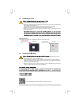
3-2 Drivers Installation @: Bafflers installing the drivers, fret install the operating system. After In staling the operating system, Insert the motherboard driver disk Into your optical drive. Click on the massage "Tap to choose whet happens with this disc” on the leap-right coma of the screen and select "Fis Run axa. Computer, double-click the optical dive and executes he Run exe program} “Press install” will automatically scan your system and then list a of the drivers that am recommended to install.
Regulatory Statements Regulator: Notices f pe io toa third party nor be: ved any! y nashoszad purpose.
Oni is equipment has been tested and found to comply with the meets for a Class digital device, pursuant to Part 15 of the FCC Rules. These limits are designed bv provide reasonable protection against harmful interference can radiate radio frequency energy and, If aot harmful 3 raid unification ot scour in a particular installation.