
User Manual

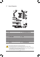


6) SYS_FAN3_PUMP (System Fan/Water Cooling Pump Header)
The fan/pump header is 4-pin and possess a foolproof insertion design. Most fan headers possess a
foolproof insertion design. When connecting a fan cable, be sure to connect it in the correct orientation
(the black connector wire is the ground wire). The speed control function requires the use of a fan with
fan speed control design. For optimum heat dissipation, it is recommended that a system fan be installed
inside the chassis. The header also provides speed control for a water cooling pump, refer to Chapter 2,
"BIOS Setup," "M.I.T.," for more information.
DEBUG
PORT
G.QBOFM
1
5) CPU_OPT (Water Cooling CPU Fan Header)
The fan header is 4-pin and possesses a foolproof insertion design. Most fan headers possess a foolproof
insertion design. When connecting a fan cable, be sure to connect it in the correct orientation (the black
connector wire is the ground wire). The speed control function requires the use of a fan with fan speed control
design.
DEBUG
PORT
G.QBOFM
1
Pin No. Definition
1 GND
2 Voltage Speed Control
3 Sense
4 PWM Speed Control
Pin No. Definition
1 GND
2 Voltage Speed Control
3 Sense
4 PWM Speed Control
Pin No. Denition
1 12V
2 G
3 R
4 B
DEBUG
PORT
G.QBOFM
1
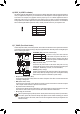
7) LED_CPU (CPU Cooler LED Strip/RGB LED Strip Header)
TheheadercanbeusedtoconnectaCPUcoolerLEDstriporastandard5050RGBLEDstrip(12V/G/R/B),
with maximum power rating of 2A (12V) and maximum length of 2m.
ConnecttheCPUcoolerLEDstrip/RGBLEDstriptotheheader.The
powerpin(markedwithatriangleontheplug)oftheLEDstripmust
be connected to Pin 1 of this header. Incorrect connection may lead
tothedamageoftheLEDstrip.
LEDStrip
1
12V
- 15 -