GA-K8VT800M AMD Socket 754 Processor Motherboard User's Manual Rev. 1001 12ME-K8VT800M-1001 Copyright © 2003 GIGABYTE TECHNOLOGY CO., LTD Copyright by GIGA-BYTE TECHNOLOGY CO., LTD. ("GBT"). No part of this manual may be reproduced or transmitted in any from without the expressed, written permission of GBT. Trademarks Third-party brands and names are the property of their respective owners. Notice Please do not remove any labels on motherboard, this may void the warranty of this motherboard.
Mother Board GA-K8VT800M Aug.
Motherboard GA-K8VT800M Aug.
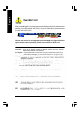
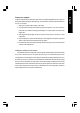
English Read Me First! When you installing AGP card, please make sure the following notice is fully understood and practiced. If your AGP card has "AGP 4X/8X (1.5V) notch" (show below), please make sure your AGP card is AGP 4X/8X. AGP 4X/8X notch Caution: AGP 2X card is not supported by VIA K8VT800M. You might experience system unable to boot up normally. Please insert an AGP Pro 4X/8X card.
Computer motherboards and expansion cards contain very delicate Integrated Circuit (IC) chips. To protect them against damage from static electricity, you should follow some precautions whenever you work on your computer. 1. Unplug your computer when working on the inside. 2. Use a grounded wrist strap before handling computer components. If you do not have one, touch both of your hands to a safely grounded object or to a metal object, such as the power supply case. 3.
English Table of Content Read Me First! ............................................................................................4 Chapter 1 Introduction ...............................................................................8 1.1 Item Checklist ........................................................................................... 8 1.2 Features Summary ................................................................................... 8 GA-K8VT800M Motherboard Layout.......................
Load Optimized Defaults .............................................................................. 56 Set Supervisor/User Password ..................................................................... 57 Save & Exit Setup .......................................................................................... 58 Exit Without Saving ....................................................................................... 59 Chapter 4 Technical Reference ..................................................
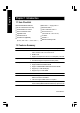
English Chapter 1 Introduction 1.1 Item Checklist The GA-K8VT800M motherboard IDE cable x 1 / Floppy cable x 1 CD for motherboard driver & utility Serial ATA cable x 1 USB + IEEE1394 Cable x 1 GA-K8VT800M user's manual Quick PC Installation Guide Audio Combo Kit x 1 GigaRAID manual (SURROUND-Kit + SPDIF Out Kit) SATA RAID manual GC-SATA Card (optional) I/O Shield DPVRM x 1 (Manual; SATA cable x 1; Power cable x 1) Motherboard Settings Label 1.2 Features Summary Form Factor — 24.4cm x 24.
On-Board Peripherals y 2 Serial ATA connectors in 150 MB/s operation mode y Built-in VIA VT8237 (Note 1) y 1 Floppy port supports 2 FDD with 360K, 720K,1.2M, 1.44M and 2.88M bytes y 1 Parallel port supports Normal/EPP/ECP mode y y y y 2 Serial ports (COMA & COMB) 8 x USB 2.0/1.
English Additional Features — PS/2 Keyboard password power on — PS/2 Mouse power on — STR(Suspend-To-RAM) — AC Recovery — USB KB/Mouse wake up from S3 — Poly fuse for keyboard over-current protection — Supports Thermal Shutdown function — Supports @BIOS — Supports EasyTune 4 Overclocking — Over Clock (CPU/DDR/AGP/PCI) by BIOS Please set the CPU host frequency in accordance with your processor's specifications.
English GA-K8VT800M Motherboard Layout CPU_FAN R_USB MS / KB LAN VIA K8T800 ATX_12V BIOS DDR1 IT8705 SUR_CEN AGP FDD SYS_FAN PCI1 AUX_IN CODEC DDR2 IDE2 F_AUDIO IDE1 GA-K8VT800M LPT COMB USB AUDIO RAM_LED COMA ATX SOCKET 754 IR PCI2 CD_IN SATA1 VIA VT8237 SATA0 F_PANEL PCI3 RTL8100C GAME BATTERY F_USB1 F_USB2 INFO_LINK SPDIF_IO PWR_LED CLR_PWD - 11 - Introduction
AMD AlthlonTM 64 processor (K8) AGP 4X/8X CPUCLK+/- (200MHz) AGPCLK (66MHz) H.T. Bus 800MHz DDR RAM 400/333/266/200MHz VIA K8T800 LAN1 RJ45 3 PCI 33 MHz 14.
English - 13 - Introduction
English GA-K8VT800M Motherboard - 14 -
English Chapter 2 Hardware Installation Process To set up your computer, you must complete the following steps: Step 1 - Install the Central Processing Unit (CPU) Step 2 - Install memory modules Step 3 - Install expansion cards Step 4 - Connect ribbon cables, cabinet wires, and power supply Step 4 Step 1 Step 2 Step 4 Step 4 Step 3 Congratulations! You have accomplished the hardware installation! Turn on the power supply or connect the power cable to the power outlet.
English Step 1: Install the Central Processing Unit (CPU) Before installing the processor and cooling fan, adhere to the following warning: 1. The processor will overheat without the heatsink and/or fan, resulting in permanent irreparable damage. 2. Never force the processor into the socket. 3. Apply thermal grease between the processor and cooling fan. 4. Please make sure the CPU type is supported by the motherboard. 5.
shown in Figure 4) prior to installing the heatsink. AMD recommends using a high thermal conductivity grease (such as Shin-Etsu types G751 or G749, or an equivalent product) for the thermal interface material rather than a phase change material. Phase change materials develop strong adhesive forces between the heatsink and processor.
English Step 2: Install Memory Modules Before installing the memory modules, adhere to the following warning: 1. When DIMM LED is ON, do not install / remove DIMM from socket. 2. Please note that the DIMM module can only fit in one direction due to the one notch. Wrong orientation will cause improper installation. Please change the insert orientation. The motherboard has 2 dual inline memory module (DIMM) sockets. The BIOS will automatically detects memory type and size.
2. Insert the DIMM memory module vertically into the DIMM socket. Then push it down. 3. Close the plastic clip at both edges of the DIMM sockets to lock the DIMM module. Reverse the installation steps when you wish to remove the DIMM module. DDR Introduction Established on the existing SDRAM infrastructure, DDR (Double Data Rate) memory is a high performance and cost-effective solution that allows easy adoption for memory vendors, OEMs, and system integrators.
English Step 3: Install expansion cards Step 3-1: AGP Card Installation 1. Read the related expansion card's instruction document before install the expansion card into the computer. 2. Remove your computer's chassis cover, screws and slot bracket from the computer. 3. Press the expansion card firmly into expansion slot in motherboard. 4. Be sure the metal contacts on the card are indeed seated in the slot. 5. Replace the screw to secure the slot bracket of the expansion card. 6.
Step 4-1: I/O Back Panel Introduction y w u x v u PS/2 Keyboard and PS/2 Mouse Connector PS/2 Mouse Connector This connector supports standard PS/2 (6 pin Female) keyboard and PS/2 mouse. PS/2 Keyboard Connector (6 pin Female) v/x USB/LAN Connector Before you connect your device(s) into USB connector(s), please make sure your device (s) such as USB keyboard,mouse, scanner, zip, speaker...etc. Have a standard USB interface. Also make sure your OS supports USB controller.
English w Parallel Port, Serial Ports (COMA / COMB) This connector supports 2 standard COM ports and 1 Parallel port. Device like printer can be Parallel Port (25 pin Female) connected to Parallel port; mouse and modem etc. can be connected to Serial ports. COMA COMB Serial Port (9 pin Male) y Audio Connectors Line In (Rear Speaker) Line Out (Front Speaker) MIC In (Center and Subwoofer) After install onboard audio driver, you may connect speaker to Line Out jack, microphone to MIC In jack.
1 3 English Step 4-2: Connectors Introduction 2 5 10 6 11 4 12 14 15 17 7 21 8 13 18 19 16 20 9 1) ATX_12V 12) SUR_CEN 2) ATX (Power Connector) 13) SPDIF_IO 3) CPU_FAN 14) CD_IN 4) SYS_FAN 15) AUX_IN 5) FDD 16) F_USB1 / F_USB2 6) IDE1 / IDE2 17) IR 7) SATA0 / SATA1 18) GAME 8) F_PANEL 19) INFO_LINK 9) PWR_LED 20) CLR_PWD 10) RAM_LED 21) BAT 11) F_AUDIO - 23 - Hardware Installation Process
English 1) ATX_12V (+12V Power Connector) This connector (ATX_12V) supplies the CPU operation voltage (Vcore). If this "ATX_12V connector" is not connected, system cannot boot. 4 3 2 Pin No. 1 Definition 1 GND 2 GND 3 4 +12V +12V 2) ATX (ATX Power Connector) AC power cord should only be connected to your power supply unit after ATX power cable and other related devices are firmly connected to the motherboard. Pin No. 11 20 GA-K8VT800M Motherboard - 24 - 1 10 Definition 1 2 3.3V 3.
Please note, a proper installation of the CPU cooler is essential to prevent the CPU from running under abnormal condition or damaged by overheating. The CPU fan connector supports Max. current up to 600 mA. Pin No. 1 Definition 1 2 GND +12V 3 Sense 4) SYS_FAN (System Fan Connector) This connector allows you to link with the cooling fan on the system case to lower the system temperature. Pin No.
English 5) FDD (Floppy Connector) Please connect the floppy drive ribbon cables to FDD. It supports 360K, 1.2M, 720K, 1.44M and 2.88M bytes floppy disk types. The red stripe of the ribbon cable must be the same side with the Pin1. 34 33 2 1 6) IDE1 / IDE2 (IDE1 / IDE2 Connector) Important Notice: Please connect first hard disk to IDE1 and connect CD-ROM to IDE2. The red stripe of the ribbon cable must be the same side with the Pin1.
You can connect the Serial ATA device to this connector, it provides you high speed transfer rates (150MB/sec). If you wish to use RAID function, please use it in unity with BIOS and install the correct driver to have proper operation. For details, please refer to the "VT8237_SATA_Manual.pdf" at "http:\\www.gigabyte.com.tw" . Pin No.
Please connect the power LED, PC speaker, reset switch and power switch etc. of your chassis front panel to the F_PANEL connector according to the pin assignment above.
Do not remove memory modules while RAM_LED is on. It might cause short or other unexpected damages due to the stand by voltage. Remove memory modules only when AC power cord is disconnected. + _ 11) F_AUDIO (Front Audio Connector) If you want to use Front Audio connector, you must remove 5-6, 9-10 Jumper. In order to utilize the front audio header, your chassis must have front audio connector. Also please make sure the pin assigment on the cable is the same as the pin assigment on the MB header.
English 12) SUR_CEN (Surround Center Connector) Please contact your nearest dealer for optional SUR_CEN cable. Pin No. 1 5 2 6 Definition 1 2 SUR OUTL SUR OUTR 3 GND 4 No Pin 5 6 CENTER_OUT BASS_OUT 13) SPDIF_IO (SPDIF In / Out Connector) The SPDIF output is capable of providing digital audio to external speakers or compressed AC3 data to an external Dolby Digital Decoder. Use this feature only when your stereo system has digital input function.
English 14) CD_IN (CD In Connector) Connect CD-ROM or DVD-ROM audio out to the connector. 1 Pin No. Definition 1 CD-L 2 GND 3 4 GND CD-R 15) AUX_IN (AUX In Connector) Connect other device (such as PCI TV Tunner audio out) to the connector. 1 - 31 - Pin No.
English 16) F_USB1 / F_USB2 (Front USB Connector) Be careful with the polarity of the front USB connector. Check the pin assignment carefully while you connect the front USB cable, incorrect connection between the cable and connector will make the device unable to work or even damage it. For optional front USB cable, please contact your local dealer. 2 1 10 9 Pin No.
This connector supports joystick, MIDI keyboard and other relate audio devices. Check the pin assignment while you connect the game cables. Please contact your nearest dealer for optional game cables. Pin No. 2 16 1 15 Definition 1 VCC 2 3 GRX1_R GND 4 GPSA2 5 VCC 6 7 GPX2_R GPY2_R 8 MSI_R 9 GPSA1 10 11 GND GPY1_R 12 VCC 13 GPSB1 14 15 MSO_R GPSB2 16 No Pin 19) INFO_LINK This connector allows you to connect some external devices to provide you extra function.
English 20) CLR_PWD When Jumper is set to "open" and system is restarted, the password that is set will be cleared. On the contrary when Jumper is set to "close", the current status remains. 1 Open: Clear Password 1 Close: Normal (Default) 21) BATTERY + CAUTION Danger of explosion if battery is incorrectly replaced. Replace only with the same or equivalent type recommended by the manufacturer. Dispose of used batteries according to the manufacturer's instructions. If you want to erase CMOS... 1.
English GA-K8VT800M Motherboard - 35 -
BIOS Setup is an overview of the BIOS Setup Program. The program that allows users to modify the basic system configuration. This type of information is stored in battery-backed CMOS RAM so that it retains the Setup information when the power is turned off. ENTERING SETUP Powering ON the computer and pressing immediately will allow you to enter Setup. If you require more advanced B IO S settings, please go to " Adv anced BI O S" setting menu.
English GETTING HELP Main Menu The on-line description of the highlighted setup function is displayed at the bottom of the screen. Status Page Setup Menu / Option Page Setup Menu Press F1 to pop up a small help window that describes the appropriate keys to use and the possible selections for the highlighted item. To exit the Help Window press . The Main Menu (For example: BIOS Ver. : F1) Once you enter Award BIOS CMOS Setup Utility, the Main Menu (Figure 1) will appear on the screen.
Integrated Peripherals English l This setup page includes all onboard peripherals. l Power Manag ement Setup This setup page includes all the items of Green function features. l PnP/PCI Configurations This setup page includes all the configurations of PCI & PnP ISA resources. l PC Health Status This setup page is the System auto detect Temperature, voltage, fan, speed. l Frequency/Voltage Control This setup page is control CPU’s clock and frequency ratio.
English Standard CMOS Features CMOS Setup Utility -Copy right (C) 1984-2003 Aw ard Softw are Standard CMOS Features Date (mm:dd:y y ) Wed, Jul 16 2003 Item Help Time (hh:mm:ss) 22:31:24 Menu Lev el u Change the day , month, }IDE Primary Master [None] }IDE Primary Slav e [None] }IDE Secondary Master [None] }IDE Secondary Slav e [None] Sun. to Sat. Driv e A [1.44M, 3.5"] Driv e B [None] Jan. to Dec.
The times format in . The time is calculated base on the 24-hour militarytime clock. For example, 1 p.m. is 13:00:00. C IDE Primary Master, Slave / IDE Secondary Master, Slave The category identifies the types of hard disk from drive C to F that has been installed in the computer. There are two types: auto type, and manual type. Manual type is user-definable; Auto type which will automatically detect HDD type.
English C Floppy 3 Mode Support (for J apan Area) 8Disabled Normal Floppy Driv e. (Default v alue) 8Driv e A Driv e A is 3 mode Floppy Driv e. 8Driv e B Driv e B is 3 mode Floppy Driv e. 8Both Driv e A & B are 3 mode Floppy Driv es. C Halt on The category determines whether the computer will stop if an error is detected during power up. 8NO Errors The sy stem boot w ill not stop for any error that may be detected and y ou w ill be prompted.
English Advanced BIOS Features CMOS Setup Utility -Copy right (C) 1984-2003 Aw ard Softw are Adv anced BIOS Features First Boot Dev ice [Floppy ] Item Help Second Boot Dev ice [HDD-0] Menu Lev el u Third Boot Dev ice [CDROM] Select Boot Dev ice Passw ord Check [Setup] priority [Floppy ] Boot from floppy [LS120] Boot from LS120 [HDD-0] Boot from First HDD [HDD-1] Boot from second HDD higf: Mov e Enter:Select +/-/PU/PD:Value F5:Prev ious Values F10:Sav e F6:Fail-Safe Defaults ESC:Ex it F1:Gen
English C Password Check 8Sy stem The sy stem can not boot and can not access to Setup page w ill be denied 8Setup The sy stem w ill boot, but access to Setup w ill be denied if the correct if the correct passw ord is not entered at the prompt. passw ord is not entered at the prompt. (Default v alue) GA-K8VT800M Motherboard k8vt800m_1001_b.
English Integrated Peripherals CMOS Setup Utility -Copy right (C) 1984-2003 Aw ard Softw are Integrated Peripherals IDE DMA transfer access [Enabled] Item Help On-Chip IDE Channel 0 [Enabled] Menu Lev el u On-Chip IDE Channel 1 [Enabled] [Auto] Onchip Serial ATA [Enabled] Auto-detect IDE AC97 Audio [Auto] cable ty pe USB 1.1 Controller [Enabled] USB 2.
English On-Chip IDE Channel 0 Enabled Enable onboard 1st channel IDE port. (Default v alue) Disabled Disable onboard 1st channel IDE port. C On-Chip IDE Channel1 8Enabled Enable onboard 2nd channel IDE port. (Default v alue) 8Disabled Disable onboard 2nd channel IDE port. On-chip SATA Disabled Disable SATA controller. Auto When there is no dev ice to be plugged in IDE1 or IDE2, SATA controller w ill remap to IDE controller. Enabled Set SATA Mode manually.
English C USB Keyboard Support When USB key board is installed, please set at Enabled. 8Enabled Enable USB Key board Support. 8Disabled Disable USB Key board Support. (Default v alue) C USB Mouse Support When USB mouse is installed, please set at Enabled. 8Enabled Enable USB Mouse Support. 8Disabled Disable USB Mouse Support. (Default v alue) C Onboard H/W LAN 8Enabled Enable onboard H/W LAN function. (Default Value) 8Disabled Disable this function.
English C Onboard Serial Port 2 8Auto BIOS w ill automatically setup the port 2 address. 83F8/IRQ4 Enable onboard Serial port 2 and address is 3F8. 82F8/IRQ3 Enable onboard Serial port 2 and address is 2F8. (Default v alue) 83E8/IRQ4 Enable onboard Serial port 2 and address is 3E8. 82E8/IRQ3 Enable onboard Serial port 2 and address is 2E8. 8Disabled Disable onboard Serial port 2.
8290 Set Midi Port Address to 290. 8300 Set Midi Port Address to 300. 8330 Set Midi Port Address to 330.(Default Value) 8Disabled Disable this function. English CMidi Port Address C Midi Port IRQ 85 Set Midi Port IRQ to 5. 810 Set Midi Port IRQ to 10. (Default Value) - 48 - k8vt800m_1001_b.
English Power Management Setup CMOS Setup Utility -Copy right (C) 1984-2003 Aw ard Softw are Pow er Management Setup ACPI Suspend Ty pe [S1(POS)] Item Help x USB Dev ice Wake-Up From S3 [Disabled] Menu Lev el u Soft-Off by PWRBTTN [Instant-Off] [S1] AC Back Function [Soft-Off] Key board Pow er On [Disabled] Mouse Pow er On [Disabled] PME Ev ent Wake Up [Enabled] Set suspend ty pe to ModemRing Resume [Enabled] Pow er On Suspend under ACPI OS Resume by Alarm [Disabled] x Date (of Month
8Instant-off Press pow er button then Pow er off instantly . (Default v alue) 8Delay 4 Sec. Press pow er button 4 sec to Pow er off. Enter suspend if button is pressed less than 4 sec. C AC Back Function 8Memory Sy stem pow er on depends on the status before AC lost. 8Soft-Off Alw ay s in Off state w hen AC back. (Default v alue) 8Full-On Alw ay s pow er on the sy stem w hen AC back. C Keyboard Power On 8Passw ord Enter from 1 to 5 characters to set the Key board Pow er On Passw ord.
English C Resume by Alarm You can set "Resume by Alarm" item to enabled and key in Data/time to pow er on sy stem. 8Disabled Disable this function. (Default Value) 8Enabled Enable alarm function to POWER ON sy stem. If RTC Alarm Lead To Pow er On is Enabled. Date ( of Month) Alarm : Ev ery day , 1~31 Time ( hh: mm: ss) Alarm : (0~23) : (0~59) : (0~59) GA-K8VT800M Motherboard k8vt800m_1001_b.
English PnP/PCI Configurations CMOS Setup Utility -Copy right (C) 1984-2003 Aw ard Softw are PnP/PCI Configurations PCI 1 IRQ Assignment [Auto] Item Help PCI 2 IRQ Assignment [Auto] Menu Lev el u PCI 3 IRQ Assignment [Auto] Dev ice(s) using this INT: Display Cntrlr -BUS 1 Dev 0 Func 0 higf: Mov e Enter:Select +/-/PU/PD:Value F10:Sav e F5:Prev ious Values F6:Fail-Safe Defaults ESC:Ex it F1:General Help F7:Optimized Defaults Figure 6: PnP/PCI Configurations PCI 1 IRQ Assignment Auto 3,4, 5,7,
English PC Health Status CMOS Setup Utility -Copy right (C) 1984-2003 Aw ard Softw are PC Health Status Vcore OK Item Help DDR25V OK Menu Lev el u +3.
English Frequency/Voltage Control CMOS Setup Utility -Copy right (C) 1984-2003 Aw ard Softw are Frequency /Voltage Control CPU Host Clock Control [Disabled] Item Help x CPU Host Frequency (Mhz) 200 Menu Lev el u PCI/AGP Frequency (Mhz) 33/66 higf: Mov e Enter:Select +/-/PU/PD:Value F10:Sav e F5:Prev ious Values F6:Fail-Safe Defaults ESC:Ex it F1:General Help F7:Optimized Defaults Figure 8: Frequency /Voltage Control CPU Host Cl ock Control Note: If sy stem hangs up before enter CMOS setup u
English Load Fail-Safe Defaults CMOS Setup Utility -Copy right (C) 1984-2003 Aw ard Softw are } Standard CMOS Features Load Fail-Safe Defaults } Adv anced BIOS Features Load Optimized Defaults } Integrated Peripherals Set Superv isor Passw ord } Pow er Management Setup Set User Passw ord } PnP/PCI Configurations Sav e & Ex it Setup } PC Health Status Ex it Without Sav ing Load Fail-Safe Defaults ( Y/N) ? N } Frequency /Voltage Control higf: Select Item ESC: Quit F8: Q-Flash F10: Sav e & Ex i
English Load Optimized Defaults CMOS Setup Utility -Copy right (C) 1984-2003 Aw ard Softw are } Standard CMOS Features Load Fail-Safe Defaults } Adv anced BIOS Features Load Optimized Defaults } Integrated Peripherals Set Superv isor Passw ord } Pow er Management Setup Set User Passw ord } PnP/PCI Configurations Sav e & Ex it Setup } PC Health Status it Without Load Optimized Defaults (Ex Y/N) ? N Sav ing } Frequency /Voltage Control higf: Select Item ESC: Quit F8: Q-Flash F10: Sav e & Ex it
English Set Supervisor/User Password CMOS Setup Utility -Copy right (C) 1984-2003 Aw ard Softw are } Standard CMOS Features Load Fail-Safe Defaults } Adv anced BIOS Features Load Optimized Defaults } Integrated Peripherals Set Superv isor Passw ord } Pow er Management Setup Set User Passw ord } PnP/PCI Configurations Sav e & Ex it Setup Enter Password: } PC Health Status Ex it Without Sav ing } Frequency /Voltage Control higf: Select Item ESC: Quit F8: Q-Flash F10: Sav e & Ex it Setup Change
English Save & Exit Setup CMOS Setup Utility -Copy right (C) 1984-2003 Aw ard Softw are } Standard CMOS Features Load Fail-Safe Defaults } Adv anced BIOS Features Load Optimized Defaults } Integrated Peripherals Set Superv isor Passw ord } Pow er Management Setup Set User Passw ord } PnP/PCI Configurations Sav e & Ex it Setup Save to CMOS and EXITEx( Y/N) ? YSav ing it Without } PC Health Status } Frequency /Voltage Control higf: Select Item ESC: Quit F8: Q-Flash F10: Sav e & Ex it Setup Sav
English Exit Without Saving CMOS Setup Utility -Copy right (C) 1984-2003 Aw ard Softw are } Standard CMOS Features Load Fail-Safe Defaults } Adv anced BIOS Features Load Optimized Defaults } Integrated Peripherals Set Superv isor Passw ord } Pow er Management Setup Set User Passw ord } PnP/PCI Configurations Sav e & Ex it Setup } PC Health Status Ex it Without Sav ing Quit Without Saving ( Y/N) ? N } Frequency /Voltage Control higf: Select Item ESC: Quit F8:Q-Flash F10: Sav e & Ex it Setup A
English - 60 - k8vt800m_1001_b.
English GA-K8VT800M Motherboard k8vt800m_1001_b.
English Chapter 4 Technical Reference @BIOS™ Introduction Gigabyte announces @BIOS Windows BIOS Live Update Utility Have you ever updated BIOS by yourself? Or like many other people, you just know what BIOS is, but always hesitate to update it? Because you think updating newest BIOS is unnecessary and actually you don't know how to update it. Maybe not like others, you are very experienced in BIOS updating and spend quite a lot of time to do it. But of course you don't like to do it too much.
English Easy TuneTM 4 Introduction Gigabyte announces EasyTuneTM 4 Windows based Overclocking utility EasyTune 4 carries on the heritage so as to pave the way for future generations. Overclock" might be one of the most common issues in computer field. But have many users ever tried it? The answer is probably "no". Because "Overclock" is thought to be very difficult and includes a lot of technical know-how, sometimes "Overclock" is even considered as special skills found only in some enthusiasts.
English Flash BIOS Method Introduction Method 1 : Q-Flash A. What is Q-Flash Utility? Q-Flash utility is a pre-O.S. BIOS flash utility enables users to update its BIOS within BIOS mode, no more fooling around any OS. B. How to use Q-Flash? a. After power on the computer, pressing immediately during POST (Power On Self Test) it will allow you to enter AWARD BIOS CMOS SETUP, then press to enter Q-Flash utility.
English Load BIOS From Floppy !In the A:drive, insert the "BIOS" diskette, then Press Enter to Run. 1 File(s) xxxx .xxx 256K Total size: 1.39M F5: Refresh Free size: 1.14M DEL: Delete Where xxxx.xxx is name of the BIOS file. ! Press Enter to Run. Are you sure to update BIOS? [Enter] to contiune or [ESC] to abort ... ! Press Enter to Run. !! Copy BIOS Completed - Pass !! Please press any key to continue ... Congratulation! You have completed the flashed and now can restart system.
If you don't have DOS boot disk, we recommend that you used Gigabyte @BIOSTM program to flash BIOS. Press here. 2.Click"Start"-"Programs""GIGABYTE"-"@BIOS" 1.Click "@BIOS" (2) (1) 3.Click "P". 4.Click here. 5. Please select @BIOS sever site, then Click "OK". (3) (4) Methods and steps: I. Update BIOS through Internet a. Click "Internet Update" icon b. Click "Update New BIOS" icon c. Select @BIOSTM sever d. Select the exact model name on your motherboard e.
English II. Update BIOS NOT through Internet: a. b. c. d. Do not click "Internet Update" icon Click "Update New BIOS" Please select "All Files" in dialog box while opening the old file. Please search for BIOS unzip file, downloading from internet or any other methods (such as: K8VT800M.F1). e. Complete update process following the instruction. III. Save BIOS In the very beginning, there is "Save Current BIOS" icon shown in dialog box. It means to save the current BIOS version. IV.
The installation of windows 98SE/2K/ME/XP is very simple. Please follow next step to install the function! Stereo Speakers Connection and Settings: We recommend that you use the speaker with amplifier to acqiire the best sound effect if the stereo output is applied. STEP 1: Connect the stereo speakers or earphone to "Line Out". Line Out STEP 2 : After installation of the audio driver, you'll find an icon on the taskbar's status area.
English 4 Channel Analog Audio Output Mode STEP 1 : Connect the front channels to "Line Out", the rear channels to "Line In". Line Out Line In STEP 2 : After installation of the audio driver, you'll find an icon on the taskbar's status area. Click the audio icon "Sound Effect" from the windows tray at the bottom of the screen. STEP 3 : Select "Speaker Configuration", and choose the "4 channel for 4 speakers out put". Disable "Only SURROUND-KIT", and press "OK".
English Basic 6 Channel Analog Audio Output Mode Use the back audio panel to connect the audio output without any additional module. STEP 1 : Connect the front channels to "Line Out",the rear channels to "Line In", and the Center/Subwoofer channels to "MIC In". Line In M IC In Line Out STEP 2 : After installation of the audio driver, you'll find an icon on the taskbar's status area. Click the audio icon "Sound Effect" from the windows tray at the bottom of the screen.
English Advanced 6 Channel Analog Audio Output M ode (using Audio Combo Kit,Optional Device): (Audio Combo Kit provides SPDIF output port : optical & coaxis and SURROUND-KIT : Rear R/L & CEN /Subwoofer) SURROUND-KIT access analog output to rear channels and Center/Subwoofer channels. It is the best solution if you need 6 channel output, Line In and MIC at the same time. "SURROUND-KIT" is included in the GIGABYTE unique "Audio Com bo Kit" as picture.
English STEP 3 : Connect the front channels to back audio panel's "Line Out", the rear channels to SURROUND-KIT's REAR R/L, and the Center/Subwoofer channels to SURROUND-KIT's SUB CENTER. STEP 4 : Click the audio icon "Sound Effect" from the windows tray at the bottom of the screen. STEP 5 : Select "Speaker Configuration", and choose the "6 channel for 5.1 speakers out put". Enable "Only SURROUND-KIT" and press "OK".
English SPDIF Output Device (Optional Device) A "SPDIF output" device is available on the motherboard. Cable with rear bracket is provided and could link to the "SPDIF output" connector (As picture.) For the further linkage to decoder, rear bracket provides coaxial cable and Fiber connecting port. 1. Connect the SPDIF output device to the rear bracket of PC, and fix it with screw. 2. Connect SPDIF device to the m otherboard. 3. Connect SPDIF to the SPDIF decoder.
Jack-Sensing provides audio connectors error-detection function. Install Microsoft DirectX8.1 before to enable Jack-Sensing support for Windows 98/98SE/2000 /M E. Jack-Sensing includes 2 parts: AUTO and M ANUAL. Following is an example for 2 channels (Windows XP): Introduction of audio connectors You may connect CDROM, Walkman or others audio input devices to Line In jack, speakers, earphone or others output devices to Line Out jack, and microphone to M IC In jack.
English If you set wrong with the connectors, the warning message will come out as right picture. Manual setting: If the device picture shows different from what you set, please press "Manual Selecion" to set. GA-K8VT800M Motherboard k8vt800m_1001_t.
What is Xpress Recovery? Xpress Recovery utility is an utility for backing up and restoring O.S. partition . If the hard drive can not work properly, you can restore it to the original state. 1. It supports FAT16 、 FAT32 、 NTFS format . 2. It must be connected to IDE1 Master . 3. It's only allows you to install one O.S . 4. It must be used with IDE hard disk supporting HPA . 5. The first partition must be set as the boot partition. When the boot partition is backed up, please do not change the its size. 6.
English You can highlight the item by using the arrows keys on your keyboard and enter key to enter the menu. Text Mode: Xpress Recovery V1.0 (C) Copy Right 2003. GIGABYTE Technilogy CO. , Ltd. 1. Execute Backup Utility 2. Execute Restore Utility 3. Remove Backup Image 4. Exit and Restart BMP Mode: Xpress Recovery V1.0 (C) Copy Right 2003. GIGABYTE Technilogy CO. , Ltd. 1. Execute Backup Utility 2. Execute Restore Utility 3. Remove Backup Image 4.
English 1.Execute Backup Utility: ! Press B to Backup your System or Esc to Exit The Backup utility will scan the system automatically and back up it. The backed up data will be saved as an hidden image . 2.Execute Restore Utility: ! This program will recover your system to factory default. Press R to recover your system. Press Esc to exit Restore the backup image to the original state. 3.Remove Backup Image: ! Are you sure to remove backup image? (Y/N) Remove the backup image. 4.
English GA-K8VT800M Motherboard k8vt800m_1001_t.
English Revision ChapterHistory 5 Appendix Install Drivers Pictures below are shown in Windows XP Insert the driver CD-title that came with your motherboard into your CD-ROM drive, the driver CD-title will auto start and show the installation guide. If not, please double click the CD-ROM device icon in "My computer", and execute the setup.exe. INSTALL CHIPSET DRIVER This page shows the drivers that need to be installed for the system.
English Driver installation finished ! You have to reboot system ! Item Description n VIA 4IN1Driver VIA Chipset Driver n USB Patch for WinXP This patch driver can help you to resolve the USB device wake up S3 hang up issue in XP. n Realtek Lan Driver RealTek 10/100 LAN driver n RealTek AC97 Codec Driver Realtek Audio Driver n VIA 8237 Serial ATA Driver For VIA 8237 SATA Driver n VIA USB 2.0 Controller VIA USB 2.
This page reveals the value-added software developed by Gigabyte and its worldwide partners.
English SOFTWARE INFORMATION This page list the contects of softwares and drivers in this CD title. HARDWARE INFORMATION This page lists all device you have for this motherboard. CONTACT US Please see the last page for details. GA-K8VT800M Motherboard k8vt800m_1001_a.
Below is a collection of general asked questions. To check general asked questions based on a specific motherboard model, please log on to http://tw.giga-byte.com/faq/faq.htm Question 1: I cannot see some options that were included in previous BIOS after updating BIOS. Why? Answer: Some advanced options are hidden in new BIOS version. Please press Ctrl and F1 keys after entering BIOS menu and you will be able to see these options.
English Question 8: How do I disable onboard VGA card in order to add an external VGA card? Answer: Gigabyte motherboards will auto-detect the external VGA card after it is plugged in, so you don't need to change any setting manually to disable the onboard VGA. Question 9: Why cannot I use the IDE 2? Answer: Please refer to the user manual and check whether you have connected any cable that is not provided with the motherboard package to the USB Over Current pin in the Front USB Panel.
If you encounter any trouble during boot up, please follow the troubleshooting procedures. START Turn off the power and unplug the AC power cable, then remove all of the add-on cards and cables from motherboard. Please make sure motherboard & chassis are not short ? Yes Please isolate the short pin. No Failure has been excluded. Please make sure all jumper settings (such as CPU system bus speed, frequency ratio, voltage and etc) are set properly. Yes No Make sure the jumper setting are correct.
English A Is memory LED on and CPU fan running? No The problem could be caused by power supply, CPU, memory or CPU/memory socket itself. Yes Failure has been excluded. No Check if there is display. Yes Perhaps your VGA card / VGA slot or monitor is defective. Failure has been excluded. Turn off the system. Reboot after keyboard and mouse have been plugged in. Check if keyboard is working properly. No It is possible that your keyboard or keyboard connector is defective.
Company: Contact Person: Phone No.: E-mail Add. : Model name/Lot Number: BIOS version: Hardware PCB revision: O.S./A.S.: Mfs. Model name Size: Driver/Utility: Configuration CPU Memory Brand Video Card Audio Card HDD CD-ROM / DVD-ROM Modem Network AMR / CNR Keyboard Mouse Power supply Other Device Problem Description: & - 88 - k8vt800m_1001_a.
English Acronyms Acronyms Meaning ACPI Advanced Configuration and Power Interface APM Advanced Power Management AGP Accelerated Graphics Port AMR Audio Modem Riser ACR Advanced Communications Riser BIOS Basic Input / Output System CPU Central Processing Unit CMOS Complementary Metal Oxide Semiconductor CRIMM Continuity RIMM CNR Communication and Networking Riser DMA Direct Memory Access DMI Desktop Management Interface DIMM Dual Inline Memory Module DRM Dual Retention Mechanism
Meaning IOAPIC Input Output Advanced Programmable Input Controller ISA Industry Standard Architecture LAN Local Area Network I/O Input / Output LBA Logical Block Addressing LED Light Emitting Diode MHz Megahertz MIDI Musical Instrument Digital Interface MTH Memory Translator Hub MPT Memory Protocol Translator NIC Network Interface Card OS Operating System OEM Original Equipment Manufacturer PAC PCI A.G.P.
English GA-K8VT800M Motherboard k8vt800m_1001_a.
English - 92 - k8vt800m_1001_a.
English GA-K8VT800M Motherboard k8vt800m_1001_a.
English - 94 - k8vt800m_1001_a.
English GA-K8VT800M Motherboard k8vt800m_1001_a.
English CONTACT US Contact us via the information in this page all over the world. — Taiwan — The Netherlands Gigabyte Technology Co., Ltd. Giga-Byte Technology B.V. Address: No.6, Bau Chiang Road, Hsin-Tien, Taipei Hsien, Taiwan, R.O.C. Address: Verdunplein 8 5627 SZ, Eindhoven, The Netherlands TEL: 886 (2) 8912-4888 Tel: +31 40 290 2088 FAX: 886 (2) 8912-4004 E-mail: NL Tech.Support : 0900-GIGABYTE (0900-44422983, 0.