PCI Wireless LAN Card GN-WPMG User’s Manual http://www.gigabyte.com.tw Version 3.
Federal Communication Commission Interference Statement: This equipment has been tested and found to comply with the limits for a Class B digital device, pursuant to Part 15 of the FCC Rules. These limits are designed to provide reasonable protection against harmful interference in a residential installation. This equipment generates, uses and can radiate radio frequency energy and, if not installed and used in accordance with the instructions, may cause harmful interference to radio communications.
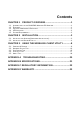
Contents CHAPTER 1 PRODUCT OVERVIEW...........................................1 1.1 1.2 1.3 1.4 1.5 INTRODUCTION TO THE GN-WPMG WIRELESS PCI ADAPTER .......................................1 FEATURES .................................................................................................................1 PHYSICAL DIMENSIONS & PACKAGING ..........................................................................1 LED INDICATOR ...........................................................................
Chapter 1 Product Overview 1.1 Introduction to the GN-WPMG Wireless PCI Adapter The GIGABYTE WPMG Wireless PCI Adapter installs quickly into your motherboard’s PCI slot, connecting wirelessly to your Wi-Fi Router - instantly transforming your PC into a wireless AP, broadening the range of your wireless network. The WPMG is fully 802.
Before beginning the installation procedures, please inspect the components to assure that they have not been damaged during shipping. The components include: Package Contents • GN-WPMG PCI Adapter • Low profile external antenna • Setup CD • Quick Start Guide In case of any missing or damaged accessories, please contact your local distributor or authorized reseller immediately. If you require returning the damaged product, you must pack it in the original packing material or the warranty will be voided. 1.
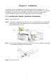
Chapter 2 Installation This chapter covers the installation of the WPMG Adapter for your desktop PC. The following sections will assist you with proper installation of the PCI Adapter, and also with installing the necessary drivers and utilities. For specific information regarding your Version of Windows, please refer to the appropriate sections as indicated 2-1. Installing the Adapter (Hardware Installation) Step 1: Power off your PC.
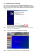
2-2. Installing the Driver & Utility After restarting your computer the Windows Found New Hardware wizard will open. When it does, please click Cancel to close it. GIGABYTE drivers and utilities offer more power and control over your new WPMG PCI Adapter than does Windows native Zero Configuration Utility. Step 1: At the Found New Hardware Wizard screen, click Cancel. Step 2: Insert the WPMG Setup CD into the CD-ROM drive. The WPMG Welcome screen window will automatically open.
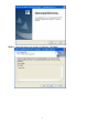
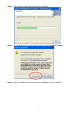
Step 5: Setup will detect your version of Windows. Click Next.
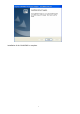
Step 6: Files will be copied and your system configured. Step 7: At the Windows XP Logo testing message, Click Continue Anyway. Step 8: When InstallShield has completed, click Finish to finish installation.
Installation of the GN-WPMG is complete.
Chapter 3 Using the Wireless Client Utility The WPMG Wireless Utility is a powerful application that helps you to configure the network card and monitor the statistics of the communication link. It appears as a square icon (green when connected, red when not) in the task bar at the bottom right corner of screen (see Figure 3-1). Figure 3-1.
Figure 3-2. Profile Manager Description of items in Figure 3-2 is as follows: Profile Setting A profile can be saved for various wireless settings in different environments, i.e. home, office, or the coffee shop. Every session uses a profile (even if it’s the Default profile). To Create a new profile, just click the “Create…” button. Profile Name: Create a profile name of your choice. Network SSID: Specify which Network name to connect to (Default: ANY) Wireless Mode: The type of radio mode (802.
Create a Profile Name, Network SSID Name, and select Network Type & Wireless Mode to use for this profile. (see Figure 3-3) Figure 3-3. Network Info Profile Name: Create a name for your new profile, a useful name is one that is both descriptive and short. Network SSID: Define which Network SSID your profile will connect to. Note, SSID Names are case sensitive, the name must match exactly or your profile won’t associate. Default is BLANK (associate with any SSID).
Figure 3-4. Security Description of items in Figure 3-3 is as follows: Authentication Mode: Users can select from a range of different security modes. (Default: Open System). Encryption Method: Select from the drop down box the desired encryption method. Shared Key - This is when both the sender and recipient share a secret key. Auto Switch WPA-PSK - A user sets a static key or "Passphrase" as with WEP.
on “Configure WEP Keys” and select either ASCII or HEX based keys. Click Next > to proceed with Profile Configuration. Step 3: Set Wireless Protocol Settings Wireless Protocol Screen Figure 3-5 – Protocol Screen Do Not Change settings (Keep original settings): Leave this checked to keep default settings in place (recommended) for Power save, Preamble, Transmit Rate, Fragment Threshold, and RTS/CTS Threshold. Or, if you wish, uncheck this option so as to manually configure these settings.
Figure 3-6. New Profile Complete – Summary Screen The wireless settings for this profile will be summarized on the Complete screen. Click Finish to complete new profile configuration. 3.2. Network Status Tab The Network Status tab displays the current association information about the Adapter connection with a wireless network.
Figure 3-7. Network Status Description of items in Figure 3-9 is as follows: Select Profile Shows the current connection profiles. New profiles can be loaded by simply selecting them from this drop-down list. Remember, every connection uses a Profile, even if it’s the profile. Signal Strength The relative strength of the adapter’s association with the Router or Access Point. Link Information Link Status: The current connection status, you’ll either be connected or not-connected.
Internet Protocol (TCP/IP) DHCP Option: Display if DHCP (automatic assignment of client IP address) is enabled (or disabled) for the current profile. IP Address: Subnet Mask: The current IP Address of the WPMG network adapter. The IP Subnet which the WPMG network adapter belongs to. Default Gateway: The IP Address of the network gateway. IP address of your wireless Router. Also known as the Channel Throughput Window Displays transmit & receive throughput as a function of time.
Network Filter Display Peer-To-Peer stations: When Checked, only displays P2P configured Access Points. Display 802.11g Access Points: When checked, only displays 11g Access Points or Routers (no 11b Access Points will be displayed). Display 802.11b Access Points: When checked, only displays 11b Access Points or Routers (no 11g Access Points will be displayed). Filter (Button): channel.
3.4. Statistics Tab The Statistics tab shows you the number of packets sent and received by the Adapter (see Figure 3-11) Figure 3-9. Statistics Description of items in Figure 3-11 is as follows: Signal Strength The relative strength of the adapter’s association with the Router or Access Point. Transmit Total Packet: Number of packets transmitted successfully. Unicast Packet: Number of unicast packets transmitted successfully, excluding packets transmitted successfully with more than one retry.
RTS Success: Representing the number of successful Ready To Send RST Failure: Value representing the failed Ready To Send. ACK Error: Representing the number of failed acknowledgements. Receive Total Packet: Number of RTS frames successfully received CTS (Clear To Send) from AP. Unicast Packet: Number of RTS frames fail to receive CTS from AP. Multicast Packet: Number of frames received successfully. Duplicate Frames: Representing the duplicate frames received.
Region Code (Location) – The region which the current firmware has been localized to. Firmware Version - Hardware version number of the Adapter’s EEPROM. MAC Address – The hardware address of the Adapter. NDIS Driver Version – The Adapter’s network driver interface specification version. Configuration Utility Version – The GIGABYTE configuration utility version number.
Appendix A Troubleshooting This troubleshooting guide provides answers to some common problems which you may encounter while installing or using GIGABYTE Wireless Adapters. Contact the GIGABYTE Wireless Technical Support Team at www.giga-byte.com if you encounter problems not mentioned in this section. Problem: Cannot connect to an AP Advice: z Make sure the SSID for the Wireless PCI Adapter is the same as the Access Point. z Make sure the security settings are the same as that of Access Point.
Appendix B Specifications 1. System Host Interface PCI (low profile) 1 bracket standard size Operating Voltages 3.3V+/- 5% 2. RF Performance Frequency Bands 2412-2483.5MHz (subject to local regulations) Modulation Technology OFDM and DSSS Modulation Techniques 64QAM, 16QAM, QPSK, BPSK, CCK, DQPSK, DBPSK Data Rates Peak Output Power 54, 48, 36, 24, 18, 12, 9, 11, 6, 5.
Appendix C Regulatory Information CE Mark Warning: This is a Class B product. In a domestic environment, this product may cause radio interference, in which case the user may be required to take adequate measures. FCC Statement: This equipment has been tested and found to comply with the limits for a Class B digital device, pursuant to Part 15 of the FCC Rules. These limits are designed to provide reasonable protection against harmful interference in a residential installation.
Appendix D Warranty Limited Warranty Statement (1-Year Warranty) Thank you for purchasing the GIGABYTE Product. This limited warranty statement will provide you one year warranty starting from the purchase date.
FCC Caution: 1. This device complies with Part 15 of the FCC rules. Operation is subject to the following two conditions: (1) This device may not cause harmful interference, and (2) This device must accept any interference received, including interference that may cause undesired operation. 2. This device and its antenna(s) must not be co-located or operating in conjunction with any other antenna or transmitter. 3.