
Installation Guide

APPROVED BY THE
POSTMASTER GENERAL
U. S.
MAIL
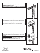
4. MOUNTING BOARD ASSEMBLY (FIG. 4)
Position the mounting board 2 1/2” from the front of the cross arm and center
left and right. Secure the mounting board using 4 (#6 x 1 5/8”) deck screws.
4. LA ASAMBLEA DE PLACA
(FIG. 4)
Ubicar la placa 2 1/ 2” desde la frente del brazo de cruz y centro izquierda y
derecho. Asegurar la placa que usa 4 (#6 x 1 5/8”) cubierta atornilla.
FIG. 5
FIG. 3
5. MAILBOX INSTALLATION
(FIG. 5)
NOTE: On Model #CCK, remove alignment nails before installing mailbox.
Place the mailbox over the mounting board and secure with 4 (#6 x 1 5/8”)
deck screws.
5. LA INSTALACIÓN DE BUZÓN
(FIG. 5)
LA NOTA: Sobre el Modelo# CCK, quitar clavos de alineación antes de
instalar buzón. Poner el buzón sobre la placa y adjuntar con
4 (#6 x 1 5/8”) cubierta atornilla.
FIG. 4
DPKCCK55-05
MADE IN
U.S.A.
TAYLORSVILLE, MS 39168
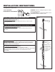
3. POST ASSEMBLY (FIG. 3)
Secure the cross arm to the post using the 2 (#8 x 2 1/2”) deck screws.
3. LA ASAMBLEA DE POSTE
(FIG. 3)
Adjuntar el brazo de cruz al poste que usa el 2 (#8 x 2 1/2”) cubierta atornilla.