
User's Manual

apmcomm confidential
apm6658/6659 WiFi 802.11 b/g/n & BT2.1+EDR Dual Radio Module
Product Information Data Sheet
Page 16 of 30
apm Communication, Inc. – TEL: 886-3-666-1188 – FAX: 886-3-666-8033
Website: http://www.apmcomm.com – E-mail:
sales@apmcomm.com
apmcomm Proprietary and Confidential – Product information is subject to change without notice.– May 30 2011
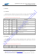
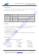
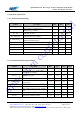
Pin #
Pin name
Pin #
Pin name
Pin #
Pin name
13 BT_SD_CS
36 BT_PIO[0]
14 BT_UART_TX
37 BT_PIO[3]
15 BT_UART_RX
45 BT_SPI_CLK
*BT_VDD_PADS voltage power level must be the same as WL_VDD_PADS_0_7
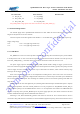
1-6 External Voltage Source
The external supply rails to apm6658/6659 should have less than 10mV rms noise levels between 0 to 10 MHz.
Single tone frequencies are also to be avoided.
Transient response of external regulators used should be <= 5us for WiFi and <= 20us for Bluetooth, respectively.
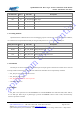
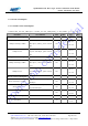
Supply voltage range
1.8V 1.8V+/- 5% (ripple Vpp<10mV rms)
3.3V 3.3V +/-5% (ripple Vpp<10mV rms)
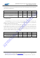
1-6-1 WiFi Reset
WL_RESETn is an active low reset input that is internally filtered using the internal low frequency clock oscillator
to avoid spurious resets. A reset occurs after the signal has been asserted for between 250 and 375us. This pin may be
tied to WL_VDD_PADS_0_7 if unused; otherwise it should be asserted for at least 1ms to force a reset.
The power supply supervisor monitors WL_VDD_CORE (internal module voltage) to trigger a power-on-reset.
This occurs when the supply falls below 1.05V (typical) in normal operation or 0.825V (typical) in deep sleep, and ends
when the supply exceeds 1.10V (typical). Glitches of up to 30mV and 2.5us duration, which could be caused by large
load steps, will not trigger a reset.
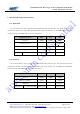
Each of the internal processors has its own independent watchdog timer to detect and recover from erroneous
software operation. These are typically configured with a timeout of 1.5s, but this may be increased up to a maximum of
64s for reduced power consumption. The watchdogs are enabled at power-on and continue operating while WiFi is in
deep sleep.
During all forms of reset most digital I/O pins (including both bidirectional pins and dedicated inputs or outputs)
default to high impedance with weak internal pull-downs. The only exceptions are WL_RESETn and WL_SPI_CS
which both have pull-ups, and the SDIO/CSPI bus which is on an independent reset domain. The SDIO/CSPI host
interface is only fully reset by the WL_RESETn pin or the power supply supervisor; other forms of reset leave the host
interface initialized but simply clear the I/O Enable bit for function 1.
Following a reset, WiFi automatically generates safe clocks for internal use. If an external reference clock is
connected to WL_CLK then this is assumed to be at the maximum supported frequency, otherwise the PLL free runs at