
User's Manual

apmcomm confidential
apm6658/6659 WiFi 802.11 b/g/n & BT2.1+EDR Dual Radio Module
Product Information Data Sheet
Page 15 of 30
apm Communication, Inc. – TEL: 886-3-666-1188 – FAX: 886-3-666-8033
Website: http://www.apmcomm.com – E-mail:
sales@apmcomm.com
apmcomm Proprietary and Confidential – Product information is subject to change without notice.– May 30 2011
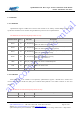
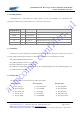
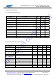
1-5-4 Debug SPI Pins
apm6658/6659 has a SPI interface for debug primarily. The lab tools, PSTOOL, can communicate with
apm6658/6659 BT part using the SPI protocol over a connection to an LPT port.
Debug SPI Name
Pin #
Pin Name Description
MISO 46 BT_SPI_MISO
Debug SPI data output
MOSI 50 BT_SPI_MOSI
Debug SPI data input
CLK 45 BT_SPI_CLK
Debug SPI clock
CS 51 BT_SPI_CS
Debug SPI chip select, active low
VDDIO 18 BT_VDD_PADS Serial I/O VDD
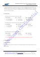
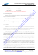
1-5-5 PIO Pins
The PIO pins are used to implement user defined input and output signals to and from the module such as external
interrupts, LED controlled output and other user-defined I/Os. Each PIO can be independently controlled.
z BT_PIO[0]: LED Bluetooth RX activities
z BT_PIO[2]: Bluetooth external clock request out
z BT_PIO[3]: Bluetooth external clock request in.
z BT_PIO[4]: The module selects the UART interface by reading BT_PIO[4] at boot-time. When BT_PIO[4] is low,
the UART interface is enabled.
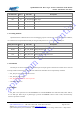
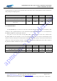
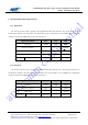
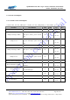
1-5-6 Power Pins
The following list shows the pins referenced to BT_VDD_PADS.
Pin #
Pin name
Pin #
Pin name
Pin #
Pin name
1 BT_PCM_IN
16 BT_UART_RTS
46 BT_SPI_MISO
2 BT_PCM_OUT
17 BT_CLK32K
50 BT_SPI_MOSI
10 BT_UART_CTS
20 BT_PIO[4]
51 BT_SPI_CSB
11 BT_SD_CLK
22 BT_PIO[2]
55 BT_PCM_CLK
12 BT_SD_CMD
32 BT_RESETB
56 BT_PCM_SYNC