
User's Manual

Intel® Centrino® Wireless-N 105 (Canyon Peak)
Intel® Centrino® Wireless-N 135 (Canyon Peak w/Bluetooth)
Intel® Centrino® Wireless-N 2200 (Marble Peak)
Intel® Centrino® Wireless-N 2230 (Jackson Peak 1)
Intel® Centrino® Advanced-N 6235 (Jackson Peak 2)
Hardware Specification, Rev. 2.2
Intel Confidential
473288
26
CyP, CYP w/Bluetooth hardware devices shall not support PCI Express* ASPM L0s power state
, and Shall support the L1 state that has high value as a Power saving state.
Not supporting L0s leads to measures that need to be taken in the Platform level to disable
the L0s ability in the Root side (chip-set/ICH side) or else a system hang may occur;
For these devices below steps must be taken to limit the L0s ASPM State
During normal ASPM initialization:
Scan each PCI Express* Root Port for the JP1, JP2, MP, Cy or CyP+Bluetooth Wireless
Ethernet Controller PCI Vendor/Device IDs.
For all Controllers listed above, when enabling ASPM, disable L0s for the root port (ICH Side)
regardless of the support reported. Disabling L0s for the root port should be done via the Link
Control Register (Offset 10h) [1:0]. These values should be restored during an S3 resume.
Note: The device driver shall disable the L0s on its side (endpoint) and shall enable L1a
to maintain low Power consumption capabilities.
Repeat the steps for all applicable network controllers in the system.
Microsoft Windows Vista* (and Microsoft Windows 7*) may Override the BIOS ASPM Settings:
JP1, JP2, MP, CyP or CyP+Bluetooth (need to be replaced with official naming/Part Number)
hardware devices present and native PCI Express support is enabled via _OSC method, and
then the FACP Bit IAPC_BOOT_ARCH (bit 4) needs to be set. This will leave ASPM control in
the hands of the platform/system BIOS.
FACP bit, if set, indicates to the OSPM that it must not enable OSPM ASPM control on the
platform.
No issue is expected with BIOS that does not use OSC method.
information regarding the IAPC_BOOT_ARCH bit.
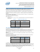
3.4 Mini Card DC Specifications
For Mini Card DC Specification refer to PCI Express Mini Card Electromechanical Specification
and Input Power and Voltage Tolerance ECN. The Max Power (as max defined in the Mini Card
Spec) is 2000mW =>667mA (need at least 2 Power Pins of the 5 exists in the Mini Card spec,
Max limit for each Pin is 500mA).
3.5 Wireless Disable
3.5.1 Wi-Fi Hardware RF Disable
The W_Disable# input signal on Pin 20 of the Mini Card system connector allows the hardware
to disable the Wi-Fi RF circuitry.
The W_Disable# signal is an active low signal that when driven low by the platform disables
Wi-Fi radio operation. The assertion and de-assertion of the W_Disable# signal is
asynchronous to any platform clock. All transients resulting from mechanical switches need to
be de-bounced by platform circuitry.
This signal is capable of:
Minimum Sink Current to ground = 1 mA per card
Note: The 1mA value is taken from the PCI Express Mini Card electrical Specification.
However, the JP1, JP2, MP, CyP, CyP w/Bluetooth case should be able to drive a much
lower current when the W_Disable# signal is active low (~50uA).
In normal operation, the card must stop any RF activity within seconds after the W_Disable#
signal is asserted. The hardware must assure that the disable operation is not dependent on