
User's Manual


Intel® Centrino® Wireless-N 105 (Canyon Peak)
Intel® Centrino® Wireless-N 135 (Canyon Peak w/Bluetooth)
Intel® Centrino® Wireless-N 2200 (Marble Peak)
Intel® Centrino® Wireless-N 2230 (Jackson Peak 1)
Intel® Centrino® Advanced-N 6235 (Jackson Peak 2)
Hardware Specification, Rev. 2.2
Intel Confidential
473288
17
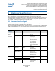
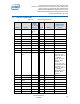
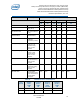
Pin #
Name
Buffer
/State
(Power-Up
Reset)
Pin #
Name
Buffer/State
(Power-Up
Reset)
37
GND
38
USB D +
39
+3.3Vaux
40
GND
41
+3.3Vaux
42
NC
43
GND
44
LED_WLAN#
Open Drain
45
C-Link_CLK
-Internal Pull
– Down ~100
kΏ
- Clink pins
should not be
used in non –
Intel®AMT
platforms
46
LED_WPAN#
Open drain
47
C-Link_DAT
48
NC
49
C-Link_RST#
-CL_RST is
active low
- CL_RST is
'low' when
AMT is
disabled
50
GND
51
W_DISABLE#_
2.
Internal Pull –
Up ~59K
typical
(Minimum:
42K.
Maximum:
88K)
52
+3.3Vaux
Note: Pins 37, 43 will be driven to GND state (This complies with Mini Card Specification
rev 1.1 Input Power ECN).
Note: The led pins (Pin#44 LED_WLAN# and Pin #46 LED_WPAN) configure to true open
drain output (disconnect the Internal Pull Down resistor) after the device is powered.
Open Drain output means that these pins output -state (Hi-Z).
Note: Pin #24 is disconnected on board, as in previous product generations.
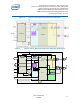
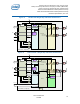
3.2.1 No Connect (NC) Signals
Express Mini Card Electromechanical Specification as well as reserved pins that are currently
not in use.
3.2.2 Power
All power pins are connected to a power bus that should be tied to 3.3V Vaux via the
connector.