
User Manual


Power Interface
Rev 1.2 Apr-05 Proprietary and confidential 23
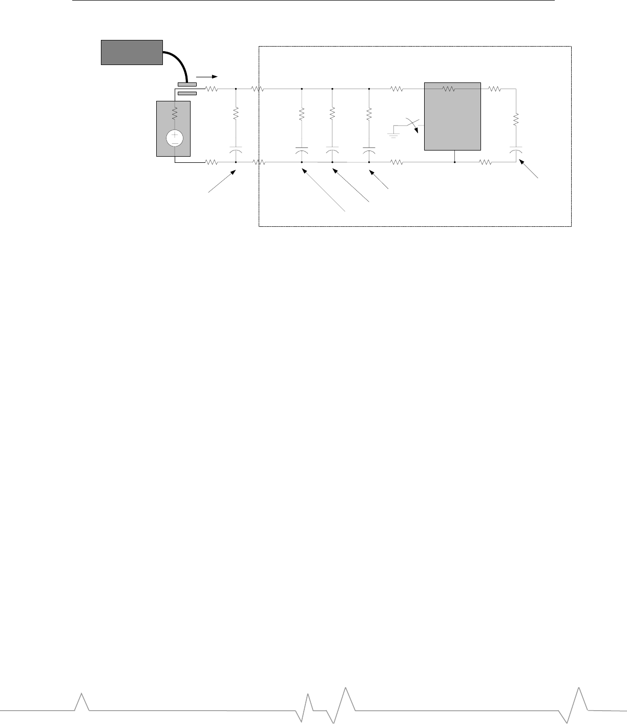
The second event is more important to module integration, and occurs when the
host asserts the ON/OFF signal to power up the EM. This event enables the
power management system of the EM, charging several internal regulator output
capacitors. Sufficient capacitance must be added to the host power rail to limit
the inrush current and stabilize the supply of power to the EM.
Figure 5 (page 22) and Figure 6 (page 24) show typical inrush current
measurements at room temperature when the host deasserts the W_Disable#
signal to power up the EM. Note that the current spikes are staggered because the
EM internal regulators switch on at slightly different times. In some
circumstances, depending on temperature and the components in use, two or
more regulators may switch on at the same instant. The host power system must
be designed to handle this scenario. Note that the peak current is dictated by the
equation: IPEAK = VBATTERY / RSERIES.
RSERIES is the sum of:
• The path from the positive terminal of the battery to the PWR pins of the EM
to the ground point thru the regulator pass element and output capacitor, and
• The path from the negative terminal of the battery to the GND pins of the
EM regulator
Figure 5 shows a 700 mA inrush from the host battery without the use of large
decoupling caps. A minor dip in VBATT results.
REG
PWR (1,2,3,4,5)
GND
(6,53,54,57,58,59,60)
ON/OFF
(18)
Current
+3.8VDC
LI-ION BATTERY PACK
LI-ION
CELL
250m
LDO pass
element
1 ohm typ
ESR
80m
8.5m 2.8m
1.7m
2.2m
1uF
ESR
20m
ESR
20m
38m
Cin
2x 1uF
10m
32m
Chost
2x 33uF
Current Probe
EM BOARD
Regulator input capacitor
Regulator
output
capacitor
ESR +
trace Z
60m
RF Cap
4.7uF
EM board decoupling cap
Host decoupling caps
2x33uF
Cin
2x 1uF
ESR +
trace Z
40m
EM board decoupling cap
15m