
User Manual


PCI Express MiniCard Hardware Integration Guide
16 Proprietary and confidential 213XXXX
location for receiver desense measurements. The unit is placed in a call and set to
generate peak output power, either through a test mode, or by configuring the
base station simulator to issue the appropriate command. The unit is then
positioned for maximum power as determined by the call box.
Sensitivity vs. frequency
Sensitivity is defined as the input power level in dBm that produces a FER of
.5%. Sensitivity should be measured at all CDMA frequencies across the band. In
the US PCS band for example, there are 25 physical channels with a spacing of
50 KHz. The first CDMA channel is CH25.
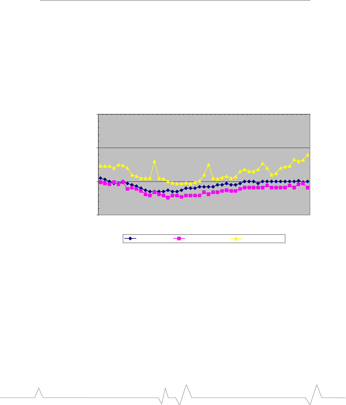
Figure 2: US PCS sensitivity measurements
-110
-105
-100
-95
25
75
125
175
225
275
325
375
425
475
525
575
625
675
725
775
825
875
925
975
1025
1075
1125
1175
Channel
Sensitivity dBm
Connectorized OTA, Ext Antenna OTA, Int Antenna
Figure 2 shows typical test results for the US PCS band for both conducted and
over-the-air connections. The conducted (or “connectorized”) measurements
were made using an RF coaxial cable connection. The over-the-air measurements
were made using both an external antenna and a typical device antenna.
In this test, the external antenna performed best—the expected result if a high
efficiency antenna with some gain is used. The internal antenna has less gain than
the external antenna, so the internal antenna’s performance is offset above the
external antenna. The antenna gain must be known to determine whether the
offset is strictly the result of antenna gain or if broadband desense is present.
Narrowband desense can be seen at channels 325, 625, and 925.