
Datasheet

66
Gepco International, Inc. P.800.966.0069 P. 847.795.9555 F. 847.795.8770 www.gepco.com
VIDEO CABLES
VIDEO CABLES
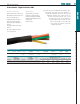
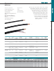
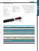
Multi-element coax and twisted-pair snake cable that uti-
lizes miniature type coax for reduced size and weight.
Coaxial construction is identical to single VDM250 for
low attenuation, low return loss, and excellent
broadband shielding. The 61801EZ type analog
audio single-pair features low-loss 22 gage
conductors and is easy to strip and terminate.
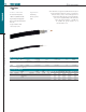
The all-weather TPE master jacket is abra-
sion resistant, durable, and remains flexi-
ble in cold temperature environments.
Composite A/V: Thin Profile
Features & Benefits
Thin Profile
Low Attenuation & Crosstalk
Flexible
Easy to Terminate
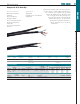
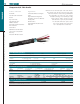
61801EZ Single-pairs
VDM250 Coaxials
Individually Shielded & Jacketed
Pairs & Coaxials
Color Coded
Additional Overall Foil Shield
100% Sweep Tested (Coaxial
Elements)
All-weather TPE Master Jacket
Applications
Standard Definition Serial Digital
Video
High Resolution Analog Video
Microphone or Line Level Balanced
Analog Audio
Portable Snakes
Ideal for ENG or Electronic Field
Production
Coax Mechanical Specifications
Conductor Insulation (Type, OD) Shield Coax Jacket (Type, OD)
25 AWG (7x33) Stranded BC Gas-injected Foam PE, .099” 95% TC Braid, 100% Foil PVC, .154”
Single-pair Mechanical Specifications
Conductor Insulation (Type, OD) Color Code Shield Drain Jacket (Type, OD)
22 AWG (7x30) Stranded TC PE, .008” Red & Black 100% Foil (Bonded) 22 AWG (7x30) Stranded TC PVC, .138”
Overall Mechanical Specifications
Overall Shield Overall Common Drain Master Jacket
100% Foil 20 AWG (10x30), Stranded TC TPE, Black
Individual Mechanical Specifications
Part # # of Coaxials Coax Color Code # of Single Pairs Single-pair Color Code Nominal OD Approx. Weight
VA2/2TP 2 Black & White 2 Brown & Red (Base 10) .430” 95 lbs/Mft
VA2/3TP 2 Black & White 3 Brown, Red & Orange (Base 10) .485” 115 lbs/Mft
Coax Electrical Specifications
Impedance
Return Loss
(100kHz-1GHz)
Capacitance
Cond. DCR
per Mft/Shield
DCR per Mft
Vel.
of
Prop.
Attenuation (dB per 100 ft)
1
MHz
3.6
MHz
10
MHz
71.5
MHz
135
MHz
270
MHz
360
MHz
720
MHz
1
GHz
75 S (+/-3)
>21dB 16.5 pF/ft
30.0 S/4.8 S
82% 0.47 0.91 1.43 3.45 4.61 6.46 7.48 10.80 12.80
Single-pair Electrical Specifications
Capacitance Cond. DCR Drain DCR
34 pF/ft between conductors,
62 pF/ft between one conductor and another tied to shield
15.3 S/Mft 15.3 S/Mft