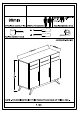
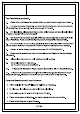
FLOOR AREA CEILING HEIGHT| 22MX1.0M 22M . oo minim (rua s APPROXIMATE ASSEMBLY TIME | 2 PEOPLE FOR ASSEMBLY REQUIRED ASSEMBLY SPACE = REQUIRED ASSEMBLY TOOLS ASSEMBLED DIMENSIONS 853.5mm NOTE : THE MAXIMUM WEIGHT THIS PRODUCT CAN HOLD KGS.
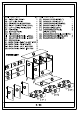
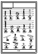
NO. PART LIST QTY NO.
Top Tips before you start! 1. Please check that all parts are present before you start the assembly of your furniture. 2. For ease and speed of assembly,we recommend that before you commence each step of the assembly,that you identify all the parts required for that step. 3. For larger items, please ensure that you have sufficient space and people ( as indicated on page 1 ) to assemble your product safely 4.
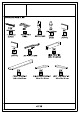
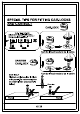
SPECIAL TIPS FOR FITTING CAM-LOCKS AND CAM BOLT =) CAM LOCK \‘-fl WHEN FITTING CAM-LOCK ENSURE STARTING POSITION IS CORRECT BEFORE YOU INSERT CONNECTING CAM BOLT TURN CLOCKWISE UNTIL SECURE vi@| @@ % "’l CORRECT WRONG @ # Cam bolt head needs to be in center DRAWER CAM-LOCK Cam bolt head needs to be in center CAM BOLT Tighten until shoulder is flush with panel.
Hinges Adjustment Facilities A Lateral adjustment B.
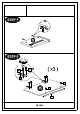
SAFETY WARNING : It is recommended that you fit the anti-tip bracket to this item to avoid tipping and causing injury. FITTING OF ANTI-TIP BRACKET STEP: Insert screws through bracket into per-drilled holes in cabinet. STEP 2 : Make a mark on the wall through the bracket. Drill a hole in the wall and insert the earplug.