
User's Manual

FIELD EQUIPMENT
NUSEIS
Geophysical Technology Inc Field Equipment Page | 17
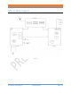
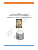
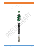
Figure 9
• A rubber grommet is used on top of the geophone for compression of the geophone into the
bottom case of the NRU.
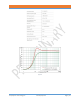
• Resistance, impedance, noise and distortion tests ensure the quality of the geophone sensor.
LED indicators and NuSite tools help QC the test results.
Hardware
• The NRU electronics are protected by a 2-part clamshell, as well as shock absorbing compression
rings and the high strength design of the case assembly.
o The M series clamshell also encompasses the battery.
o The N series clamshell encompasses the electronics only.
• See the electronic block diagram.
• There are 4 boards.
o Antenna Board (AB)
▪ BLE Bluetooth device and antenna. Used for status broadcasting and NuSite
communications
▪ Optional TransferJet device and antenna. For data uploading, parameter and
firmware programming wirelessly
▪ GPS module and connection to the GPS antenna
▪ Serves as motherboard for digital and analog board interconnection
o Digital Board (BB)
▪ LED status indicators
▪ Connector for the internal battery pack.
▪ Battery charging circuit, including the pogo connections to the Cap Assembly
Charge MIMs.
▪ USB circuit, including the pogo connections to the Cap Assembly USB MIMs.
▪ uSD card. Stores the seismic data in proprietary format. Easily swappable
▪ Processor
o Analog Board (TB)
▪ LED status indicators