
User's Manual
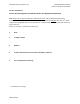
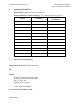

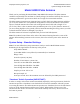
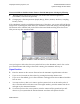
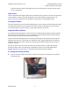
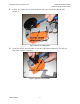
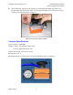
Table Of Contents

Geophysical Survey Systems, Inc. Model 62000 Palm Antenna
System Settings and User Notes
reflection from the ground. The higher that you raise the antenna, the further apart will be
the two waveforms.
Gain Check
GSSI recommends allowing the SIR System to automatically set gain levels. Place the antenna in
contact with the concrete so that the SIR System sets values which are appropriate for the
material. Be sure to hold down the “Deadman” switch while re-initializing the gains.
The Marker Switch
The black button on the top of the antenna housing is a remote marker switch. Pushing this while
collecting data will put a user mark in the data. This is useful for situations when you want to
record the location of a surface feature or other important item in the data.
Integrated Survey Wheel
Your Palm antenna incorporates a survey wheel for collecting data in Distance (Survey Wheel)
mode. While it is still possible to collect Continuous (Time based) data with the Palm antenna,
the survey wheel cannot be removed from the antenna.
GSSI recommend calibrating the survey wheel by following the instructions presented in your
SIR-System manual. For convenience the calibration value is approximately 1697 counts/foot
(5568/m). Note that this value is subject to change and you should calibrate your own survey
wheel for accuracy.
The survey wheel can be moved to the side of the antenna in order to collect data with the
antenna elements in the cross-polarized configuration. Please see the GSSI Handbook for
RADAR Inspection of Concrete for a discussion of the benefits of this technique.
To change the wheel position
1.
Remove the three thumb screws (blue enclosures in Figure 2) securing the survey wheel
attachment plate.
Figure 2: Remove thumb screws.
MN31-290 Rev - 3