
User Manual


Geophysical Survey Systems, Inc. Model 5103 Antenna
System Settings and User Notes
Manual MN30-191 Rev -A 2
Signal Position
Place the antenna on the ground and use the Automatic Signal Position selection. The system will servo
and place the direct coupling pulse at the top of the time range window.
To test that you have the correct position, raise the antenna off the ground and you will observe on your
system that the antenna transmit pulse will separate from the reflection from the ground. The higher that
you raise the antenna, the further apart will be the two pulses.
To assure that the direct coupling pulse (time zero) is recorded the user should place the signal Position
servo in the manual mode. The signal should then be moved down in the time range window until the
entire surface pulse is visible and there is some ‘dead time’ or flat trace visible above the direct coupling
pulse in the time range window.
Gain Check
The surface pulse should be about 2/3 the width of the screen. If it is greater, reduce the Gains
manually. If the signal appears too small you can manually increase the Gains, but the first gain point
should never exceed 10dB, the last gain point should not exceed 65dB.
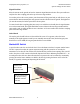
Marker/Kill Switch
A special marker switch is used with the 5103. It has a deadman switch and a separate marker button.
The FCC requires that when the operator stops interacting with the system for ten seconds, the
transmitter is to be shut off. This will also close the data file that you have been acquiring. Thus you will
need to keep the red “kill” switch on the handle depressed at all times. Releasing the handle for 2 - 10
seconds pauses data collection. Data collection that is in pause mode can be restarted by momentarily
pressing the marker button. Markers are added to the data by pressing the button on the end of the
handle, or by quickly releasing and depressing the kill switch.
Red “kill” switch. Must
be depressed during
calibration and data
collection.
Marker button.
Press to add
markers to data.