
User's Manual


Geophysical Survey Systems, Inc. Model 5101 Antenna
www.geophysical.com System Settings and User Notes
Manual MN31-124 Rev - 1
Model 5101 Antenna
The Model 5101 antenna represents the state of the art in shallow earth or deeper concrete
imaging. The high frequency allows excellent resolution at a penetration depth that is greater
than antennas in the 1.5 GHz range. This antenna is appropriate in areas where higher
frequencies do not have adequate penetration power and lower frequencies do not provide
acceptable resolution.
Note: The Model 5101 antenna cannot at present be used with the large, three-wheeled utility
cart. It can only be used with the small survey minicarts. Use of the Model 5101 for data
collection on bridge decks requires the small minicart (Model 614 or 615) and the extension arm.
System Setup - Standard Settings
Note: You must follow these setup instructions exactly to use the Model 5101 antenna.
Positioning of the signal will be the last step in the process.
Setup Mode: Manual
System Run Mode: Survey Wheel (recommended) or Continuous
Range: 20-40 ns
Number of Gain Points: 5
Vertical Low Pass Filter (FIR): 3000 MHz
Vertical High Pass Filter (FIR): 225 to 250 MHz
Vertical High Pass Filter (IIR): 10 MHz
Samples per Scan: 512
Bits per Sample: 16
Scans per Second: Set to the maximum scan rate allowed by the SIR System used
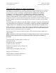
Signal Position
Place the antenna on the concrete floor and
use the Automatic Signal Position selection.
You may need to try this more than once to
get the system to lock on to the surface
pulse. If you are using the antenna with a
minicart, remember that you must have the
red “deadman” switch on the minicart’s
handle depressed.
To test that you have the correct position,
raise the antenna off the ground and you will
observe on your system that the antenna
transmit pulse will separate from the reflection from the ground. The higher that you raise the
antenna, the further apart will be the two pulses.