
User Manual

Geophysical Survey Systems, Inc. Model 5100 Antenna
System Settings and User Notes
Manual MN31-108 Rev - 1
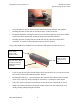
Model 5100 Antenna
The Model 5100 antenna has greatly improved performance over previous high frequency antennas.
Not only is the frequency higher, but the antenna has the ability to see objects at very close distances.
The Model 5100 can only be used with a “deadman” switch with the SIR-20 or SIR-3000 control
units. These systems are designed to limit the antenna at or below its maximum rated pulse repetition
frequency of 200 KHz.
System Setup - Standard Settings
Note: You must follow these setup instructions exactly to use the Model 5100 antenna. Positioning of
the signal will be the last step in the process.
Setup Mode: Manual
System Run Mode: Survey Wheel (recommended) or Continuous
Range: 6-12 ns
Number of Gain Points: 3
Vertical Low Pass Filter: 3000 MHz
Vertical High Pass Filter: 400 MHz
Samples per Scan: 512
Bits per Sample: 16
Scans per Second: Set to the maximum scan rate allowed by the SIR System used
Signal Position
Place the antenna on the concrete floor and use the Automatic Signal Position selection. You may need
to try this 2 to 3 times to get the system to lock on to the surface pulse. If after 3 tries the surface pulse
is not in the signal window, point the antenna into the air and again try the Automatic Position.
To test that you have the correct position, raise the antenna off the ground and you will observe on your
system that the antenna transmit pulse will separate from the reflection from the ground. The higher that
you raise the antenna, the further apart will be the two pulses.
Gain Check
The surface pulse should be about 2/3 the width of the screen. If it is greater, reduce the Gains
manually. If the signal appears too small you can manually increase the Gains, but the first gain point
should never exceed 10dB.