
User's Manual


LX-80 User Manual
Page 7 of 32
3. Connector Pin-Out
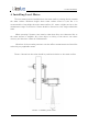
The level meter uses robust IP66 circular M12 connector with 12 positions and the
mating cable is also delivered with the level meter. The connector and cable details are
shown on Picture 1. The Table 2 gives detailed description for each pin.
Picture 1. Level meter connectors
Table 2. Connector and cable pin-out
P i n
N o .
W i r e C o l o r
P i n N a m e
P i n D e s c r i p t i o n
1
White
GND
This pin should be connected to the ground (negative)
pole of the power supply.
2
Brown
+Vin
The power supply for the Radar Level Sensor is
provided on this pin. The Radar Level Sensor power
supply voltage must be in the range 9 VDC to 27 VDC,
and the power supply must be able to provide at least
0,65W.
3
Green
RS232 – TxD
RS-232 data transmit signal.
4
Yellow
RS232 – RxD
RS-232 data receive signal.
5
Grey
GND
Signal ground.
6
Pink
CAN – H
CAN2.0B high signal.
(optional)
7
Blue
CAN – L
CAN2.0B low signal.
(optional)
8
Red
V+
Output power supply (=Vin) for supply of external
optional equipment and for use with analog 4-20mA
output
9
Orange
RS485 – D-
RS-485 data transmitter/receiver low signal.
10
Dark Red
RS485 – D+
RS-485 data transmitter/receiver high signal.
11
Black
SDI-12
SDI-12 communication interface
12
Purple
4 – 20 mA
Output
Analog 4 – 20 mA output