
User Manual


www.geolink.io
User Manual (1.3) OpenTracker 2 15
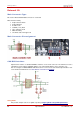
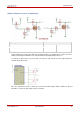
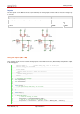
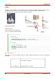
Inputs
The two inputs on the Main Connector (IN1 and IN2) are analog inputs and are able to measure voltages up
to 32 volts.
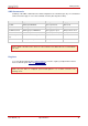
Operating conditions
Analog input Resolution (Vpin = Vinput * 22 / (220+22))
8 bit
MIN
MAX
V input
0VDC
32VDC
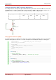
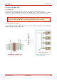
Using the Inputs (IN1 / IN2)
This example shows how to read the analog inputs on the Main Connector (External IO) and print the output
to the debug port.
1. #define DEBUG 1 //enable debug msg, sent to serial port
2. #define debug_port SerialUSB
3.
4. #ifdef DEBUG
5. #define debug_print(x) debug_port.print(x)
6. #else
7. #define debug_print(x)
8. #endif
9.
10. // Variables will change:
11. int outputValue;
12. int sensorValue;
13.
14.
15. void setup() {
16. // put your setup code here, to run once:
17.
18. }
19.
20. void loop() {
21.
22. // Read IN1 Value
23. // read the analog in value:
24. sensorValue = analogRead(AIN_EXT_IN1);
25. // map it to the range of the analog out:
26. outputValue = sensorValue * (242.0f / 22.0f * ANALOG_VREF / 1024.0f);
27.