AT-P2400E1000TP GeoDesy Kft. H-1116 Budapest, Kondorfa str. 6-8. Telefon: 06-1-481-2050 Fax.: 06-1-481-2049 E-mail: info@geodesy.hu http://www.geodesy.
Table of contants 1 2 Introduction ....................................................................................................................... 4 1.1 What is FSO? ............................................................................................................... 4 1.2 Why is it important? .................................................................................................... 4 1.3 Optical Free-space Transmission.....................................................
9.1.6 SNMP Setup ....................................................................................................... 31 9.1.7 Auto tracking setup ............................................................................................ 32 9.1.8 Security............................................................................................................... 34 9.2 Tracking software update .......................................................................................... 35 9.
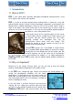
1 Introduction 1.1 What is FSO? FSO is free space optics provides point-point broadband communications using Laser Light as the transmission medium. FSO is a state of art data communication method which is based on a very old communication solution. Ancient Chinese developed a protection system against the Mongol tribes, building watchtowers within the line of site to other towers.
very hard receiver sensitivity. These two factors combined to provide one of the best performing FSO systems on the market today. To meet the demands for every higher bandwidth, GeoDesy FSO continues to invest heavily in research and development with the newest product line which offers Gigabit speeds being launched. This manual describes the GeoDesy FSO series of free space laser transmission system.
1.3 Optical Free-space Transmission The principle used in free space laser transmission is very similar to the one is used for fibre optic transmission. The difference is while fibre optic devices use electronics and optics optimized for transmission to the air. Also one can observe to the similarity in the transmission properties. No galvanic contact, no ground-loops, no need for surge protection, noise immunity, long distances, high bandwidth.
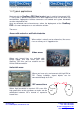
1.4 Typical applications Most typically the GeoDesy FSO Next product are is used to interconnect LANs. The system is protocol transparent, thus other applications also can be taken into consideration. Appropriate interface converters are needed and system bandwidth must be matched for that. Here we collected some circumstances, where the deployment of the GeoDesy FSO is the most adequate as a cost effective solution.
2 Interfaces for the Giga Next Series 2.1 1000Mbps TP interface The GeoDesy FSO series products are designed to provide easy-to-use and costeffective solution for interconnecting Local Area Networks. By utilizing standard Category 5e cable and using standard IEEE802.3af interface the deployment of the system is easier than ever before. The transparent and wire speed data transfer together with virtually zero latency assures the easy integration of the system in all environments.
3 Sites of installation 3.1 Key factors of operation There are four key issues that the site survey has to shed light on. Proper system operation cannot be guaranteed without satisfying all of the four requirements. Clear line of sight - The entire optical path between the two ends must be free of any obstacles. It not only means that one has to see the other side, but other possible sources of disturbance should also be taken into consideration.
Preferred installation Pay attention to sites Avoid (*) Concrete wall Brick wall Soft materials Chimneys Wooden constructs Metal masts or Frames Hidden heat isolations, like Styrofoam Behind window Old constructs Microwave towers (*) In cases where installations are listed under “AVOID” cannot be avoided than special mounting accessories to be designed and special installations must be used. It is not only the building that has to be solid, but the support structure too.
3.3 Distance measurement Because the units were designed, and calibrated for certain distance operations the higher distance will decrease the availability. GeoDesy FSO pre-calibrates and pretests every unit shipped to the customer. To ensure that the unit you are about to buy fits to the needs, the first step is to measure the distance. The best way to measure it is by GPS (Global Positioning System), these units are accurate enough to determine the distance between two points.
4 Eye safety There are no two installation spots of the same kind, the buildings or structures, the available space and the accessibility of the place will be different in each case. Nevertheless, as a general rule it is very important to select the installation site so that nobody can look directly into the transmitter.
5 The mounting bracket In the following chapter you will find detailed description of the bracket fastenings. 5.1 Mounting brackets for the AT Series GeoDesy FSO provides the mounting bracket and all the necessary components for AT series units.
Packet list for the bracket: 4pcs 8x110 screw for bracket fixing 4pcs 12x100 plastic wall-plug for bracket fixing 4pcs 8ᶲ washer 4pcs 8ᶲ spring washer 4pcs 8x16 hex head screw 4pcs 8x22hex head screw 2pcs RJ45 plug 1pcs 6x8 cross-head screws 1pcs 8ᶲ seaqling washer 2pcs PG11cable gland blanking plag 1pcs short M6 screw Mounting Hole Patterns GeoDesy Kft. H-1116 Budapest, Kondorfa str. 6-8. Telefon: 06-1-481-2050 Fax.: 06-1-481-2049 E-mail: info@geodesy.hu http://www.geodesy.
6 System connection Before turning the system on check and read chapter 6.3 very carefully. 6.1 Connection Layout Network Uplink FSO (reserved) FSO head FSO Power Supply GeoDesy Kft. H-1116 Budapest, Kondorfa str. 6-8. Telefon: 06-1-481-2050 Fax.: 06-1-481-2049 E-mail: info@geodesy.hu http://www.geodesy.
6.2 Power Supply connection and the laserhead Important: Please only solder UV proof 2wire cooper cable into its place as in below photos. The power supply shall only be used indoors. GeoDesy Kft. H-1116 Budapest, Kondorfa str. 6-8. Telefon: 06-1-481-2050 Fax.: 06-1-481-2049 E-mail: info@geodesy.hu http://www.geodesy.
6.3 Transport fixing removal Before turning ON the system, Please do the following. 1. Cut the cable tie below the laser head and pull it out of the laser head. 2. Unscrew the long M6 screw below the laser head. 3. Cover the hole where the long M6 screw was using the short M6 screw (this is packed in the bag of screws of brackets) and also cover the two holes (where the cable tie was) by screwing the 2pcs cable gland blanking plug (also packed in the bag of screws of brackets). GeoDesy Kft.
7 System installation 7.1 On the table test Warning! Do not look either into the transmitter or the receiver optics because at this distance even the reflected laser beam can be dangerous to your eyes. Operating the system on much shorter distance than presumed originally can cause saturation or even permanent damage to the receiver. Always use optical attenuators for this kind of test. The on-the-table test needs careful planning and careful use during the test period.
7.1.1 Alignment of the AT-2400E1000TP The first step after the unit was placed to the bracket, and the units facing each other. On the back of the receiver you can find the LEDs and LCD screen for the local received level and the remote received level. This help will be very useful because as soon as you have received – which is very easy to achieve – you can see the effect of your local sides movement to the other side. For further information please check the Meanings of the LCDs chapter. 7.
4.screen AT mode: Manual / Auto SPWR:0-10 AGC:0-1G:0-9 SPWR: (1-9=ok): Important that these signal power has no any connection to the receiving level. 0 - too little light. 10: too much light. 1-9: Tracking is working, but the optimum range is:3-8. 5.screen SGM pos.: Pos,Pos AFMode: auto or manual Signal position: [0-100], [0-100] tracking signal position. X and Y position (in %), so the system seeks 50 and 50 %.
Factory reset/First boot: After turning ON the status LED on the laser head will flash for about 30 seconds then the laser head will change to Auto Tracking (AT) status, after that the LED will be continuously yellow. Tracking enabled (status LED: yellow): If the status LED is yellow then the AT system is enabled. Manual set Mode (status LED: green): After booting the equipment will automatically turn to AT mode.
Focus set mode: (status LED: dark): By pressing the Change Status button for 3 seconds the Status Led will turn OFF (dark), after that the laser head will turn to focus mode. You can change the size of the laser beam by pressing the buttons as in below sketch. 800 m< 500m1000m <500m 7.4 System layout with GEO20 Beside the GeoDesy laser equipment (buckup) you can only use GeoDesy’s GEO20 Radio equipment. In the case of using a different backup solution, could cause undesired operation.
7.4.1 Connecting to your Network You can upgrade the system. GeoDesy Kft. H-1116 Budapest, Kondorfa str. 6-8. You can upgrade the Network Interface. Telefon: 06-1-481-2050 Fax.: 06-1-481-2049 E-mail: info@geodesy.hu http://www.geodesy.
8 The mounting bracket 8.1 How to use the alignment unit 1 step The fixing screws and the fine fixing scews should be loose.Pllease see a pictures No1. 2 step Untighten the 2 screws seen an pictures No2. 3 step Align the laser head horizontally using 2 of the 12 available positions.(Positions are an 30° scale) 4 step Align the laser head vertically. GeoDesy Kft. H-1116 Budapest, Kondorfa str. 6-8. Telefon: 06-1-481-2050 Fax.: 06-1-481-2049 E-mail: info@geodesy.hu http://www.geodesy.
5 step Tighten the screwsseen a picture No5. 6 step Align the laser head to best position using the fine alignment screws. Please see Picture No6 how to direct these screws. 7 step Tighten the fixing screws as an picture No7. GeoDesy Kft. H-1116 Budapest, Kondorfa str. 6-8. Telefon: 06-1-481-2050 Fax.: 06-1-481-2049 E-mail: info@geodesy.hu http://www.geodesy.
8.2 Alignment of the heads Turn ON the equipment. Turn the equipment to Manual Set Mode(status LED:green).(see 7.3 UserInterface) By pressing the right-left buttons both at the same time then the AT system stops in the middle position, the Position LEDs will turn twice confirming that. After that you can start the alignment using the alignment unit. Using the telescope and alingment unit. Target Side B with the crosshair bulit in to the head on Side A.
9 Management 9.1 Features The Inband network-monitoring unit is a newly developed highly featured monitoring for GeoDesy FSO manufactured laser links. This high quality equipment allows the user to monitor the link statuses such as detector voltage transmitter status, and many other features of the Laser link. Nevertheless, this chapter is intended to describe the usage of this network monitoring, and its connection and relationship with the GeoDesy FSO laserheads.
network. Managed head: displays the managed head type. Head Serial Number: This is the head serial number and during the Activation process we will ask for this number. 9.1.3 Status info screen Clicking on the Device Setup you will enter the main status information screen, which will give you good summarized information of the device, such as status information of the transmitters, detector level, or temperature values.
RX OK: this information is showing that the receiver is enabled. It basically means that there is valid signal with necessary strenght is received in the local end. 9.1.4 Device setup The device setup screen leads you to the main monitoring options. Here the alarms can be set and main information about the Laser head. Device name: uniqe identifier of the device Managed head: Type of the laserhead Temperature alert level: when the temperature reach this value, the alarm will be triggered.
9.1.5 Network Setup Clicking on the Network Setup link you can have access to the Ethernet module of the system, this will make easy access to the IP number and/or port settings. These settings are sensitive setting and some of them cannot be restored by the user. Please always do the changes with extra care! If you have doubt in any step, do not hesitate to contact the technical support of the manufacturer website for further information.
MDI/MDI-X, some old switch types might report incompatibility here it can be switched off. (Auto MDI/MDI-X can be turned off even in the Xs systems) NPASW mode: Network Port Auto SWitchover FSO: Transmition throgh FSO. Backup: Backup channel (FSO disabled) Auto: If NPASW mode is Auto then the actual channel chosen by the software is ON.
Trap UDP Port: the SNMP trap UDP port number (1…1000) the preset value is 161 Traps: The Laserhead is sending two different traps: LaserHeadAlarm (OID: 1.3.6.1.4.1.17857.0.1201) This trap will be sent after any of the alarms will go on (for alarm setting please see chapter 5.4) LaserHeadAlarmCancel (OID: 1.3.6.1.4.1.17857.0.1202) After the alarm goes off this trap will be sent 9.1.7 Auto tracking setup Tr-SW version: The Auto Tracking software version number. Mode: Automatic : normal tracking mode.
Manual (auto tracking off): you can manually move the laser head using the userinterface or the management (will refer to that on next page). Userinterface: green LED. Signal power(1-9=ok): Important that these signal power has no any connection to the receiving level. 0 - too little light. 10: too much light. 1-9: Tracking is working, but the optimum range is:3-8. Signal position: [0-100], [0-100] tracking signal position. X and Y position (in %), so the system seeks 50 and 50 %.
Here you can adjust the Auto Tracking manually. STEP (X;Y) by…: The tracking would go to the value written here. Auto-Focus system: Here you can adjust the size of the laser beam. In order to reach the above Auto Focus system you will have to adjust the MODE button at the Userinterface. In Auto tracking mode, by pressing the down botton the Auto Focus mode will turn ON or turn OFF (the 4 leads above it will blink twice).
9.2 Tracking software update 1. Connect the RS232 cable between the laser head and the PC. 2. Press and keep pressing the right button of the User Interface while you restart the laser head. The laser head will turn to upgrade mode and you can see the status LED blinking yellow. 3. Start the Total Commander program and start PIC32.exe program. 4. Choose COM1 port. 5.Click ont the Connect button. 6.Click on Erase button. 7. Click on Load Hex File button and then choose the attached .
9.Click on Run application button: the laser head will restart with the new software. 10. Click on the Disconnect button and close the program. 9.3 Network Interface software update 1. Connect the RS232 cable between the laser head and the PC.(Network Interface RS232) 2. Enter into the management of the laser head and into the device info. 4.Click on the „Update” button. 5.Click on OK button. 6. Start the Total Commander program and start PIC32.exe program. 7. Choose COM1 port. 8.
9.Click on Erase button. 10. Click on Load Hex File button and then choose the attached .HEX file (new software) 11.Click on the Program button. 12.Click on Run application button: the laser head will restart with the new software. GeoDesy Kft. H-1116 Budapest, Kondorfa str. 6-8. Telefon: 06-1-481-2050 Fax.: 06-1-481-2049 E-mail: info@geodesy.hu http://www.geodesy.
13. Click on the Disconnect button and close the program. 9.4 Mandatory Management Activation Thank you for buying our product. Please read this note carefully. From software version (3.2.1218/R090x)! The product you have bought has fully functional management software, which has limitation only in time. The unit activation request should be sent to activation@geodesy-fso.com.
- All GigaNext-Series(1000 MB/s) will be limited after the 90th day, when the whole bandwidth will be blocked, except the management system. 9.5 Reloading factory default settings Should you need to reload the original factory settings follow the steps below. 1. turn ON the switch of Power Adapter 2. wait 3 seconds 3. then turn OFF the switch of the Power Adapter 4. above procedure 3 times. 5.