GD-GEO20
Table of contents 1 Conventions Used in this Document ..................................................................................... 4 Abbreviation List ................................................................................................................... 5 2 Packing list ............................................................................................................................ 7 3 Introduction .....................................................................
7.2.10 Wireless ACL ........................................................................................................ 43 7.2.11 Traffic Shaping ...................................................................................................... 44 7.2.12 Port Forwarding ..................................................................................................... 45 7.2.13 Static Routes ........................................................................................................
1 Conventions Used in this Document The following typographic conventions and symbols are used throughout document: Additional information that may be helpful but which is not required. Important information that should be observed. bold Menu commands, buttons, input fields, links, and configuration keys are displayed in bold italic References to sections inside the document are displayed in italic.
Abbreviation List Abbreviation Description ACL Access Control List AES Advanced Encryption Standard AMSDU Aggregated Mac Service Data Unit AP Access Point CRC Cyclic Redundancy Check DHCP Dynamic Host Control Protocol EAP Extensible Authentication Protocol GHz Gigahertz GMT Greenwich Mean Time.
UAM Universal Access Method VLAN Virtual Local Area Network VoIP Voice over Internet Protocol WDS Wireless Distribution System WEP Wired Equivalent Privacy WISPr Wireless Internet Service Provider roaming WLAN Wireless Local Area Network WPA Wi-Fi Protected Access WPA2 Wi-Fi Protected Access 2
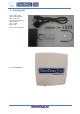
2 Packing list 1 piece power cable 1 piece power adapter 1 piece connector 1 piece bent threaded rod 1 piece bracket 1 piece screw 4 pieces nuts + 1 piece user manual CD 1 piece GD-GEO20-TP
3 Introduction GD-GEO20 offers reliable, great performance and cost-effective point-to-multipoint outdoor and indoor wireless solutions perfectly suited for access technology, private network and hotspots. Beside that APC (Access Point/Customer Premises Equipment) can be used for a light point-to-point applications. APC works in unlicensed 2.4 or 5 GHz frequency band, which is attractive solution for quick and simple network creation with minimum investment.
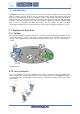
Point to Multipoint Scenario 3.1.3 Light PTP GD-GEO20 supports access point and station operating modes, therefore point-to-point can be created From AP and Station or from 2 Station’s or from 2 AP‟s. For simplicity two Stations can be used Because they have integrated directional antennas. There are available options for SISO and MIMO PTPs. Maximum achievable real data throughput is up to 160 Mbps.
4 Device Setup The default product address is 192.168.2.66. To access the Web management interface, configure your PC with a static IP address on the 192.168.2.0 subnet with mask 255.255.255.0. Connect the AP device in to the same physical network as your PC. Open the W eb browser and type the default IP address of the AP device https://192.168.2.66/ and the login page will be loaded.
Step 6. Navigate to the Configuration | Network tab and choose the Router network mode with NAT enabled, Static IP enabled on W AN side, LAN settings with DHCP server enabled (to loan an IP addresses for connected clients) on LAN side and click Save Apply: Step 7.
Step 8. Verify connection.
4.2 Station Setup Follow the steps for initial wireless client setup that will be connected to the previously configured AP (refer to the section Initial AP Setup). Step 1. Connect an Ethernet cable between your computer and the GD-GEO20 device. Step 2. Make sure your computer is set to the same subnet as the APC, i.e. 192.168.2.150 Step 3. Start your Web browser. Step 4. Each APC devices uses following default settings: WAN IP: 192.168.2.66 Subnet mask: 255.255.255.
Step 5. Enter the default password, and then press the Login button to enter the APC web management page. Step 6. Navigate to the Configuration | Network tab and choose the bridge network mode with, Dynamic IP enabled (be sure that AP to which the device will be associated has a DHCP server running ((refer to the section Initial AP Setup for instructions)), specify the DHCP fallback settings in case the DHCP server will be unreachable and click Save Apply button: Step 7.
Step 8. Verify connection. Navigate to the Status | Network page. The Network page will show main network information about association with AP: The main Status | Information page will display wireless information of the link with access point.
The connection status must be displayed as Connected and progress bars indicating the quality of the connection must be displayed:
5 Network Mode 5.1 Bridge Mode The device can act as a wireless network bridge and establish wireless links with other APs. In this mode all LAN port and W ireless interface will be a part of the Bridge. Bridge Mode With a Bridge, all connected computers are in the same network subnet. The only data that is allowed to cross the bridge is data that is being sent to a valid address on the other side of the bridge. 5.
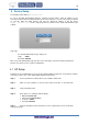
6 Device Operation 6.1 Web Management Structure The main web management menu is displayed after successfully login into the system (see the figure below). From this menu all essential configuration pages are accessed. The active menu tab is displayed in a different color: GD-GEO20 Figure 7 – Main Web Management Menu By default the Status | Information menu is activated where the main device information is displayed.
Traffic shaping – download and upload traffic control. Port forwarding – port forwarding rules (only in router network mode for AP and IPoll AP). Static routes – static route rules (only in router network mode for AP and IPoll AP). Services WNMS – set WNMS server/collector URL allowing remote device configuration and monitoring. System Alerts – set alerts which can be sent via SNMP Traps or/and SMTP notifications. SNMP – SNMP service settings allowing remote device monitoring.
7 Configuration 7.1 Status 7.1.1 Information The Information page displays a summary of status information of your device. It shows important information for the APC operating mode, network settings. System information – displays general information about the device. Wireless information – displays general information about the wireless network.
7.1.2 Status Network The Network sections displays statistics of the network interfaces and DHCP leases (depending on network mode): Figure 9 – Network Statistics Interface – displays the interface name. The SSID name is displayed in the brackets near the radio interface (and VAPs). IP address – displays the IP address of the particular interface. MAC – displays the MAC address of the particular interface. Received – displays the number of received packets.
tables with information about connected wireless clients will be displayed. Peer MAC – displays MAC address of the successfully connected wireless client. Signal – indicates the signal strength of the access point main and auxiliary antennas that the station communicates with displayed dB. Noise – displays the noise level in dBm. IEEE mode – displays the IEEE mode at which the access point communicates with the particular station.
7.2 Configuration 7.2.1 Network The Configuration | Network page allows you to control the network configuration and settings of the device. First, the device operation mode must be defined to work as a bridge or router. The content of the window varies depending on your selection: Network mode - choose the device operating mode [bridge/router] Bridge – in this mode the device works as transparent bridge interconnecting wireless network and LAN port.
IP Settings When assigning IP address make sure that the chosen IP address is unused and belongs to the same IP subnet as your wired LAN, otherwise you will lose the connection to the device from your current PC. If you enable the DHCP client, the browser will lose the connection after saving, because the IP address assigned by the DHCP server is not predictable.
Management VLAN Available only on Bridge network mode. Access to the AP for management purposes can further be limited using VLAN tagging. By defining Management VLAN, the device will only accept management frames that have the appropriate Management VLAN ID. All other frames using any management protocol will be rejected. When you specify a new management VLAN, your HTTP connection to the device will be lost.
Enable NAT – select to enable NAT (Network Address Translation), that functions by transforming the private IP address of packets originating from hosts on your network so that they appear to be coming from a single public IP address and by restoring the destination public IP address to the appropriate private IP address for packets entering the private network, the multiple PCs on your network would then appear as a single client to the W AN interface.
change hardware (router), you need to notify your ISP about MAC address change, or simply set The router’s MAC address to the MAC address of the previously router/computer. VLAN ID – specify the VLAN ID for traffic tagging on required radio interface [2-4095]. The Station devices that associate using the particular SSID will be grouped into this VLAN. WAN mode – choose Static IP to specify IP settings manually. This option needs parameters listed below: IP address – specify static IP address.
WAN mode – choose PPPoE to configure W AN interface to connect to an ISP via a PPPoE: MAC address – specify the clone MAC address if required. The ISPs registers the MAC address of the router, and allows only that MAC address to connect to their network. In such case if there is need to change hardware (router), you need to notify your ISP about MAC address change, or simply set The router’s MAC address to the MAC address of the previously router/computer.
IP address – specify the IP address of the device LAN interface. Subnet mask – specify the subnet mask of the device LAN interface. LAN DHCP Settings DHCP mode – choose disabled to disable DHCP on LAN interface. DHCP mode – choose relay to enable DHCP relay. The DHCP relay forwards DHCP messages between subnets with different sub layer broadcast domains. DHCP mode – choose server to enable DHCP server on LAN interface. IP address from – specify the starting IP address of the DHCP address pool.
7.2.4 Wireless The Wireless tab is divided in three sections: Basic, Security and Advanced configuration sections. The Basic section contains all parameters that required to configure in order have working wireless link. Security section is used to select authentication and encryption settings. Advanced section contains parameters allowing optimizing the link capacity. Before changing radio settings manually verify that your settings will comply with local government regulations.
7.2.5 Wireless Mode: Access Point Use Basic Wireless Settings to setup radio interface of the device. Basic Wireless Settings SSID – specify the SSID of the wireless network device.
Broadcast SSID – enables or disables the broadcasting of the SSID for AP. IEEE mode – specify the wireless network mode. Channel width – The default channel bandwidth for 802.11 radio is 20MHz. The 802.11n allow channel bonding in such way the total channel width becomes 40MHz. Channel – select the channel from the drop-down list or option Auto for auto channel.
Passphrase – specify WPA or WPA2 passphrase [8-63 characters]. The passphrase will be converted to key format, selected above.
Tx power – set the unit’s transmitting power at which the device will transmit data. The larger the distance, the higher transmit power is required. To set transmit power level use the slider or enter the value manually. When entering the transmit power value manually, the slider position will change according to the entered value. The maximum transmit power level is limited to the allowed value by country in which device is operating regulatory agency.
The APC will step down to the highest rate that allows data transmission. Max data rate N – choose the data rates in Mbps at which should transmit packets for the selected 802.11n mode. The APC will attempts to transmit data at the highest data rate set. If there will be an interference encountered, the APC will step down to the highest rate that allows data transmission.
WEP encryption can be either 64bit or 128bit: WEP passkey – specify the passkey, for the chosen WEP security: For WEP 64bit encryption – 5 HEX pairs (e.g. aa:bb:cc:dd:ee), or 5 ASCII characters (e.g. abcde); For WEP 128bit encryption – 13 HEX pairs (e.g. aa:bb:cc:dd:ee:ff:gg:hh:00:11:22:33:44), or 13 ASCII characters (e.g.
PEAP/ MSCHAPv2 Identity – specify the identity of the authentication to the RADIUS server. Password – specify the password of the authentication to the RADIUS server. Identity and Password on the APC must match the identity and password running on the RADIUS server's user list. Advanced Wireless Settings Advanced parameters allow configuring the device to get the best performance/capacity of the link. Tx power – set the unit’s transmitting power at which the device will transmit data.
antenna will be chosen automatically. MIMO – multiple input multiple outputs. The device will use two antennas for data transfer (two Simultaneous streams). Max data rate – choose the maximum data rate in Mbps at which should transmit packets. The APC Will attempts to transmit data at the highest data rate set. If there will be an interference encountered, The APC will step down to the highest rate that allows data transmission.
channel selection allows iPoll Access Point to select a channel which is not used by any other wireless device or, if there are no free channels available - to select a channel which is least occupied. Channel list – select the channels to create a channel list for auto channel. Security Settings Both sides (iPoll Access Point and iPoll Station) of the link must have the same security settings.
the distance, the higher transmit power is required. To set transmit power level use the slider or enter the value manually. When entering the transmit power value manually, the slider position will change according to the entered value. The maximum transmit power level is limited to the allowed value by country in which device is operating regulatory agency. Enable ATPC – select to enable Automatic Transmit Power Control (ATPC).
Basic Settings Use this section to setup basic operating settings of the iPoll Station radio. iPoll Access Point and iPoll Station will operate in 802.11n IEEE mode only. SSID – specify the SSID of the wireless network device manually, or use Scan functionality. Scan – click this button to scan for surrounding iPoll Access Points. Found network SSID‟s will be Available in drop down menu. Channel width – The default channel bandwidth for 802.11 N radio is 20/40MHz. The 802.
Transmit power – set the unit’s transmitting power at which the device will transmit data. The larger the distance, the higher transmit power is required. To set transmit power level use the slider or enter the value manually. When entering the transmit power value manually, the slider position will change according to the entered value. The maximum transmit power level is limited to the allowed value by country in which device is operating regulatory agency.
To create a new Virtual AP, click on + button to add new entry on the VAP table, then select this entry and specify required parameters: SSID – specify the unique name for the VAP [string]. Broadcast SSID – when this option is selected the particular SSID is visible during network scans on a wireless station. W hen unselected, the VAP SSID is not visible and not broadcasted to wireless stations. Quality of service (WMM) – enable to support quality of service for prioritizing traffic.
Access Control provides the ability to limit associations wirelessly based on MAC address to an AP by creating an Access Control List (ACL). Policy – define the policy: Open – no rules applied Allow MAC in the list – only listed MAC clients can connect to the AP (white list). Deny MAC in the list – only listed MAC clients can NOT connect to the AP (black list). To add new rule, press the “+” button. To remove the rule, first select the rule then press the “–” button.
Upload limit, kbps – specify the maximum upload (from Ethernet interface to wireless interface) bandwidth value in Kbps. Upload burst, kbytes – specify the upload burst size in kbytes Limit per IP traffic Use + button to create new traffic limitation rules IP address – specify IP address for which the traffic will be limited. Down rate, kbps – specify the maximum download (from wireless interface to Ethernet interface) bandwidth value in Kbps.
Enable DMZ – select to enable DMZ. DMZ opens all TCP/UDP ports to particular IP address. It allows setting up servers behind the APC. The feature is used commonly for setting up VoIP or Multi- Media servers. Public port – specify the port that will be accessed externally using the public IP address. Private host – specify the IP address behind NAT that public traffic will get forwarded to. Private port – specify the listening port on private computer behind NAT.
Enable WNMS agent – select to enable WNMS agent. Server/Collector URL – specify the URL of the WMS server to which that heartbeat notifications will be sent to. 7.3.2 System alerts The device is able to send external alerts when there are system errors. The alerts can be sent via SNMP Traps or/and SMTP notifications. Enable alerts – select to enable alert notifications on the system.
SNMP Traps Settings Manager address – specify the IP address or hostname of SNMP Trap receiver. Manager port – specify the port number of the Trap receiver. Default port number is 162. Trap community - specify the SNMP community string. This community string acts as password between SNMP manager and device by default Trap community string is "public". Use informs – select to wait for an acknowledgment from SNMP manager that trap was received.
Enable SNMP – specify the SNMP service status. Friendly name – displays name of the APC that will be used to identify the unit. This name has the same value as Friendly name in the Device settings. Link location – displays the physical location of the device. This name has the same value as Device location in the Device settings. Contact information – specify the identification of the contact person for this managed device, together with information on how to contact this person.
Configuration – choose the system clock configuration mode [NTP/Manual]. Time zone – select the time zone. Time zone should be specified as a difference between local time and GMT time. Save last known time – select to recall the timestamp that was saved on last reboot. W hen NTP is enabled, this option will set system clock to last reboot time if no NTP servers are available. NTP server – specify the trusted NTP server IP or hostname for synchronizing time with [IP address].
Enable management through HTTP – select tis option to enable or disable HTTP access to the device management. Port – specify HTTP port. Standard HTTP port is 80. HTTPS connection via the standard port 8080 is always enabled. 7.4 System 7.4.1 Administration For security reasons it is recommended to change the default administrator username and password as soon as possible. System menu allows you to manage main system settings and perform main system actions (reboot, restore configuration, etc.).
Longitude – specify the longitude coordinates of the device [specific decimal format, e.q. 54.869446]. Latitude – specify the latitude coordinates of the device [specific decimal format, e.q. 23.891058]. Both coordinates helps indicate accurate location of the device. Account settings The Administrative Account menu is for changing the administrator’s password. Default administrator Username: admin Password: admin01 logon settings are: Username – change the administrator’s username.
View system log – click to view current trace messages. The system log viewer utility provides debug information about the system services and protocols. If the device's malfunction occurs recorded messages can help operators to locate misconfiguration and system errors. Message level – specify system's message tracing level. The level determines the importance of the message and the volume of messages generated by the device.
Enable – select to enable LEDs on the device. If this option is not selected, then no LED activity will be visible on the device. RSSI thresholds – specify the RSSI threshold at which corresponding LED will switch on. The Signal LEDs are working only when the connection is established. Therefore, please make sure all wireless settings are correct and the connection is established. LAN LED – select to enable LAN LED. The red LED will be blinking on LAN activity, off – no LAN connection.
Upgrade – upgrade device with the uploaded image and reboot the system. Do not switch off and do not disconnect the device from the power supply during the firmware upgrade process as the device could be damaged.
7.5 Tools 7.5.1 Antenna Alignment The Antenna Alignment tool measures signal quality between the Station and AP. For best results during the antenna alignment test, turn off all wireless networking devices within range of the device except the device(s) with which you are trying to align the antenna. W atch the constantly updated display in the Alignment Test window as you adjust the antenna. Start – press this button to start antenna alignment. Stop – press this button to stop antenna alignment.
Last updated before – displays when the last scan was performed. The results of the Site Survey test are converted to handy two graphs: AP count and RSSI. An administrator can use this to identify the best channel for device operation that will not receive interference from adjacent APs. 7.5.
Operating with the new settings, and in case the link fails, device will be rebooted in specified minutes, thus the old settings will be set back. Reboot after – specify time in minutes, after which the device will be rebooted. Start/Stop – click to start or stop delayed reboot tool. 7.5.4 Ping This command is used to test whether a particular host is reachable across an IP network.
Destination IP or Hostname – specify hostname or IP address of the target host. Max Hops –Specifies the maximum number of hops to search for target. Start/Stop – click to start or stop traceroute tool. 7.5.6 Spectrum Analyser The Spectrum analyzer test displays detailed information about signal level of each APC unit’s Antenna on each available frequency. This enables administrator choose the best available Frequency/channel for the unit operation.
Operating frequency range – displays the channel frequency range at which the APC unit is operating currently. Maximum – color indicates the maximum achieved signal level on the appropriate frequency. Current – color indicates the current signal level on the appropriate frequency. Average – indicates average of the signal level on the appropriate frequency.iversal Access Method (UAM) Universal Access Method (UAM) is a simple Web browser based user authentication method.
8 Universal Acces Method 8.1 UAM Overview When using internal UAM, the Login page is the first page a client receives when he starts his W eb browser and enters any URL. To get access to the network, the user should enter his authentication settings: login name and password and click the login button: The GD-GEO20 could be shared by several W ireless Internet Service Providers (WISP). They are uniquely identified by specifying WISP domain name in addition to subscriber user name when logging in.
Use Security section on W ireless or VAP (depending on the interface on which the UAM will be configured) page for UAM configuration: choose the security option UAM: RADIUS Settings NAS ID – specify the NAS identifier. RADIUS server 1 – specify the name or IP address of the primary RADIUS server. RADIUS server 2 – specify the name or IP address of the secondary RADIUS server. RADIUS Secret – specify the RADIUS shared secret.
Key – upload a PEM formatted private key file. Certificate – upload a PEM formatted certificate file.
WISPr Settings WISPr location name – specify the WISPr location name. Operator name – specify the operator‟s name Network name – specify the network name ISO country code – specify the country code in ISO standard. E.164 country code – specify the country code in E.164 standard. E.164 area code – specify the area code in E.164 standard. WISPr default max bandwidth – specify the default bandwidth limitation for clients.
9 Appendix 9.1 Resetting Device to Factory Defaults Device has the capability of being reset to defaults by pinging the device with a certain packet size when the radio is booting. During the startup of the device, when the drivers of the Ethernet interfaces are loaded, the discovery daemon is started. The daemon suspends startup process for 3 seconds and waits for ICMP "echo request" packet of length 369 bytes. If the packet received, the discovery resets the device to default configuration.
9.2 RADIUS Attributes The following RADIUS attributes and messages are supported by the GD-GEO20. 9.2.1 General Attributes Attribute Description User-name (1) Full username as entered by the user. User-Password (2) Used for UAM as alternative to CHAP-Password and CHAP-Challenge.
Message-Authenticator (80) Is always included in Access-Request. If present in Access-Accept, Access-Challenge or Access-reject chilli will validate that the Message-Authenticator is correct.
Attribute Description Acct-Interim-Interval (85) If present in Access-Accept chilli will generate interim accounting records with the specified interval (seconds). MS-MPPE-Send-Key (311,16) Used for WPA MS-MPPE-Recv-Key (311,17) Used for WPA 9.2.2 WISPr Attributes Attribute Description WISPr-Location-ID (14122, 1) Location ID is set to the radiuslocationid option if present. Should be in the format: isocc=, cc≤ E.164_Country_Code>, ac≤E.
Attribute Description ChilliSpot-Bandwidth-Max-Down (14559, 5) Maximum bandwidth down ChilliSpot-Config (14559, 6) Configurations passed between chilli and back-end as name value pairs ChilliSpot-Lang (14559, 7) Language selected in user interface ChilliSpot-Version (14559, 8) Version of Chilli sending this AccessRequest