Operator's Manual Serial Number Range GR-12 GR-15 GR-20 from GR10-20000 ANSI/CSA North America South America Asia with Maintenance Information Fifth Edition Third Printing Part No.
Operator's Manual Fifth Edition • Third Printing Front Matter Important Contents Read, understand and obey these safety rules and operating instructions before operating this machine. Only trained and authorized personnel shall be permitted to operate this machine. This manual should be considered a permanent part of your machine and should remain with the machine at all times. If you have any questions, contact us. Introduction ...........................................................
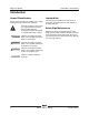
Fifth Edition • Third Printing Operator's Manual Introduction Introduction Owners, Users and Operators: Thank you for choosing our machine for your application. Our number one priority is user safety, which is best achieved by our joint efforts. We feel that you make a major contribution to safety if you, as the equipment users and operators: Danger 1 Comply with employer, job site and governmental rules.
Operator's Manual Fifth Edition • Third Printing Introduction Hazard Classification Intended Use Decals on this machine use symbols, color coding and signal words to identify the following: This machine is intended to be used only to lift personnel, along with their tools and materials to an aerial work site. Safety alert symbol—used to alert you to potential personal injury hazards. Obey all safety messages that follow this symbol to avoid possible injury or death.
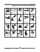
Fifth Edition • Third Printing Operator's Manual Symbol and Hazard Pictorials Definitions Symbol and Hazard Pictorials Definitions Read the operator’s manual Read the service manual Crush hazard No smoking Collision hazard Tip-over hazard Tip-over hazard Use a piece of Electrocution hazard cardboard or paper to search for leaks Electrocution hazard Explosion hazard Fire hazard Burn hazard Skin injection hazard Transport diagram Tiedown Keep away from moving parts Move machine to level gro
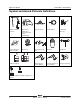
Operator's Manual Fifth Edition • Third Printing Symbol and Hazard Pictorials Definitions Maintain required clearance Only trained maintenance personnel should access compartments Chock the wheels Release brakes Grounded AC 3-wire only Replace damaged wires and cords Wheel load Lanyard anchorage point Side force Wind speed Voltage rating for power to platform Pressure rating for air Emergency lowering line to platform Maximum capacity + + + Maximum capacity including occupant, tools and tr
Fifth Edition • Third Printing Operator's Manual General Safety General Safety Part No.
Operator's Manual Fifth Edition • Third Printing General Safety 6 GR-12 • GR-15 • GR-20 Part No.
Fifth Edition • Third Printing Operator's Manual General Safety Part No.
Operator's Manual Fifth Edition • Third Printing General Safety 8 GR-12 • GR-15 • GR-20 Part No.
Fifth Edition • Third Printing Operator's Manual Personal Safety Personal Safety Personal Fall Protection Personal fall protection equipment (PFPE) is not required when operating this machine. If PFPE is required by job site or employer rules, the following shall apply: All PFPE must comply with applicable governmental regulations and must be inspected and used in accordance with the manufacturer’s instructions. Part No.
Operator's Manual Fifth Edition • Third Printing Work Area Safety Work Area Safety Electrocution Hazards Tip-over Hazards This machine is not electrically insulated and will not provide protection from contact with or proximity to electrical current. Occupants, equipment and materials shall not exceed the maximum platform capacity or the maximum platform capacity of the platform extension. Weight in trays is part of the total platform load.
Fifth Edition • Third Printing Operator's Manual Work Area Safety Do not drive over 0.5 mph / 0.8 km/h with the platform raised. Maximum capacity - GR-20 Standard platform Platform without extension 350 lbs 159kg Platform retracted 350 lbs 159 kg Platform extended – Platform only 100 lbs 45 kg Platform extended – Extension only 250 lbs 113 kg Maximum occupants 350 lbs/159 kg AWP platform Maximum occupants Do not raise the mast when wind speeds may exceed 28 mph / 12.5 m/s.
Operator's Manual Fifth Edition • Third Printing Work Area Safety Do not use the platform controls to free a platform that is caught, snagged or otherwise prevented from normal motion by an adjacent structure. All personnel must be removed from the platform before attempting to free the platform using the ground controls. Do not place or attach fixed or overhanging loads to any part of this machine. Do not place ladders or scaffolds in the platform or against any part of this machine.
Fifth Edition • Third Printing Operator's Manual Work Area Safety Operation on Slopes Hazards Collision Hazards Do not drive the machine on a slope that exceeds the slope and side slope rating of the machine. Slope rating applies to machines in the stowed position. Maximum slope rating, stowed position 30% (17°) Maximum side slope rating, stowed position 30% (17°) Note: Slope rating is subject to ground conditions and adequate traction. Fall Hazards The guard rail system provides fall protection.
Operator's Manual Fifth Edition • Third Printing Work Area Safety Limit travel speed according to the condition of the ground surface, congestion, slope, location of personnel, and any other factors which may cause collision. Explosion and Fire Hazards Do not operate the machine or charge the battery in hazardous locations or locations where potentially flammable or explosive gases or particles may be present.
Fifth Edition • Third Printing Operator's Manual Work Area Safety Electrocution/Burn Hazards Battery Safety Connect the battery charger to a grounded, AC 3-wire electrical outlet only. Burn Hazards Batteries contain acid. Always wear protective clothing and eye wear when working with batteries. Avoid spilling or contacting battery acid. Neutralize battery acid spills with baking soda and water. Do not expose the batteries or the charger to water or rain during charging.
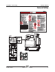
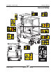
Operator's Manual Fifth Edition • Third Printing Legend Legend 1 2 3 4 5 6 7 8 9 16 Pothole guard Non-steer tire Emergency lowering valve Transport tie-down Forklift pockets Battery charger display Covers Ground controls Hydraulic oil level indicator 10 Power to platform/battery charger connection for optional inverter 11 Work station tray (if equipped) 12 Brake release pump knob (under covers) 13 Sliding mid-rail 14 Platform controls 15 Lanyard anchorage point 16 Mast GR-12 • GR-15 • GR-20 17 18 19
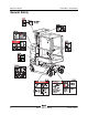
Fifth Edition • Third Printing Operator's Manual Controls Controls Ground Control Panel 1 2 3 4 5 6 7A breaker for electrical circuits Red Emergency Stop button Push in the red Emergency Stop button to the off position to stop all functions. Pull out the red Emergency Stop button to the on position to operate the machine. Menu down button Menu enter button Platform up button Platform down button Part No. 133571 7 Lift function enable button Press and hold this button to activate the lift function.
Operator's Manual Fifth Edition • Third Printing Controls 7 7 6 12 13 =+ - =+ - 8 5 5 4 9 4 3 10 11 + 14 137636 2 2 1 =- STOP STOP Platform Control Panel 1 4 Low speed lift enable button Press the horn button and the horn will sound. Release the horn button and the horn will not sound. Press and hold this button to activate the low speed platform function.
Fifth Edition • Third Printing Operator's Manual Controls 6 Proportional control handle and function enable switch for drive function Drive function: Press and hold the function enable switch to enable the drive function on the platform control handle. Move the control handle in the direction indicated by the blue arrow on the control panel and the machine will move in the direction that the blue arrow points.
Operator's Manual Fifth Edition • Third Printing Inspections Inspections Pre-operation Inspection Fundamentals It is the responsibility of the operator to perform a pre-operation inspection and routine maintenance. Do Not Operate Unless: You learn and practice the principles of safe machine operation contained in this operator’s manual. 1 Avoid hazardous situations. 2 Always perform a pre-operation inspection. Know and understand the pre-operation inspection before going on to the next section.
Fifth Edition • Third Printing Operator's Manual Inspections Pre-operation Inspection Pothole guards Be sure that the operator’s, safety and responsibilities manuals are complete, legible and in the storage container located in the platform. Be sure that all decals are legible and in place. See Inspections section. Check for hydraulic oil leaks and proper oil level. Add oil if needed. See Maintenance section. Check for battery fluid leaks and proper fluid level. Add distilled water if needed.
Operator's Manual Fifth Edition • Third Printing Inspections Function Test Fundamentals The function tests are designed to discover any malfunctions before the machine is put into service. The operator must follow the step-by-step instructions to test all machine functions. Do Not Operate Unless: You learn and practice the principles of safe machine operation contained in this operator’s manual. 1 Avoid hazardous situations. 2 Always perform a pre-operation inspection.
Fifth Edition • Third Printing Operator's Manual Inspections At the Ground Controls Test Emergency Stop 1 Select a test area that is firm, level and free of obstruction. 7 2 Be sure the batteries are connected. 3 Pull out the platform and ground red Emergency Stop button to the on position. 8 4 Turn the key switch to ground control. Test the Up/Down Functions 5 Observe the diagnostic LED readout on the platform controls.
Operator's Manual Fifth Edition • Third Printing Inspections Test Emergency Lowering 15 Activate the up function by pressing the lift enable button and platform up button, and raise the platform approximately 2 ft. / 60 cm. 16 Pull the emergency lowering knob located at the base of the machine below the mast. Use the button pattern on the platform controls to determine which of these next two function tests to perform.
Fifth Edition • Third Printing Operator's Manual Inspections 27 Press and hold the high speed lift enable button. 36 Press and hold the low speed lift enable button. 28 Press the platform up button. 37 Press the platform down button. Result: The platform should raise. The pothole guards should deploy. 29 Release the high speed lift enable button or the platform up button. Result: The platform should stop raising. 30 Press and hold the high speed lift enable button.
Operator's Manual Fifth Edition • Third Printing Inspections 44 Press the lift function button. Test the Steering 45 Press and hold the function enable switch on the control handle. Slowly move the control handle in the direction indicated by the blue arrow. Note: When performing the steer and drive function tests, stand in the platform facing the steer end of the machine. 51 Press the drive function button (if equipped). Result: The platform should raise. 46 Release the control handle.
Fifth Edition • Third Printing Operator's Manual Inspections 58 Slowly move the control handle in the direction indicated by the yellow arrow on the control panel until the machine begins to move, then return the control handle to the center position. Result: The machine should move in the direction that the yellow arrow points on the control panel, then come to an abrupt stop when the control handle is returned to the center position.
Operator's Manual Fifth Edition • Third Printing Inspections Test the Pothole Guards Note: The pothole guards should automatically deploy when the platform is raised. The pothole guards activate limit switches that allow the machine to continue to function. If the pothole guards do not deploy, an alarm sounds and the machine will not drive or steer. 69 Raise the platform. Result: When the platform is raised 4 ft / 1.2 m from the ground, the pothole guards should deploy.
Fifth Edition • Third Printing Operator's Manual Inspections Workplace Inspection Checklist Be aware of and avoid the following hazardous situations: drop-offs or holes bumps, floor obstructions or debris Do Not Operate Unless: sloped surfaces You learn and practice the principles of safe unstable or slippery surfaces machine operation contained in this operator’s manual. overhead obstructions and high voltage conductors 1 Avoid hazardous situations.
Operator's Manual Fifth Edition • Third Printing Inspections Inspection for Decals with Words Determine whether the decals on your machine have words or symbols. Use the appropriate inspection to verify that all decals are legible and in place. Part No. Decal Description Qty Part No.
Fifth Edition • Third Printing Operator's Manual Inspections Part No.
Operator's Manual Fifth Edition • Third Printing Inspections Inspection for Decals with Symbols Part No. Decal Description Determine whether the decals on your machine have words or symbols. Use the appropriate inspection to verify that all decals are legible and in place. Part No.
Fifth Edition • Third Printing Operator's Manual Inspections Part No.
Operator's Manual Fifth Edition • Third Printing Operating Instructions Operating Instructions Fundamentals The Operating Instructions section provides instructions for each aspect of machine operation. It is the operator’s responsibility to follow all the safety rules and instructions in the operator’s, safety and responsibilities manuals. Do Not Operate Unless: You learn and practice the principles of safe machine operation contained in this operator’s manual. 1 Avoid hazardous situations.
Fifth Edition • Third Printing Operator's Manual Operating Instructions Emergency Stop Operation from Platform Push in the red Emergency Stop button to the off position at the ground controls or the platform controls to stop all functions. 1 Be sure the battery pack is connected before operating the machine. 2 Turn the key switch to platform control. Repair any function that operates when either red Emergency Stop button is pushed in.
Operator's Manual Fifth Edition • Third Printing Operating Instructions To Steer To select drive speed 1 Press and hold the drive/steer function enable switch on the control handle. 2 Turn the steer wheels with the thumb rocker switch located on the top of the control handle. The drive controls can operate in two different drive speed modes while in the stowed position. When the drive speed button light is on, slow drive speed mode is active.
Fifth Edition • Third Printing Operator's Manual Operating Instructions To Position Platform To Drive 1 1 Press the lift function button. On the LCD screen, a circle below the lift function symbol will turn on. If the control handle is not moved within seven seconds of pushing the lift function button, the circle below the lift function symbol will turn off and lift function will not operate. Press the lift function button again. 2 Press and hold the function enable switch on the control handle.
Operator's Manual Fifth Edition • Third Printing Operating Instructions To select drive speed The drive controls can operate in two different drive speed modes while in the stowed position. When the drive speed button light is on, slow drive speed mode is active. When the drive speed button light is off, fast drive speed mode is active. To determine the slope grade: Measure the slope with a digital inclinometer OR use the following procedure.
Fifth Edition • Third Printing Operator's Manual Operating Instructions Operational indicator codes If the platform controls LED or ground controls LCD diagnostic readout displays an operational indicator code such as LL, the fault condition must repaired or removed before resuming machine operation. Push in and pull out the red Emergency Stop button to reset the system. To Extend and Retract Platform (if equipped) 1 Step on the platform extension release pedal.
Operator's Manual Fifth Edition • Third Printing Operating Instructions Battery Level Indicator Use the LED diagnostic readout to determine the battery level. Note: When a blinking LO code appears on the platform controls LED display, the machine must be taken out of service and charged, otherwise all machine functions will be disabled. Battery and Charger Instructions Observe and Obey: Full Charge Do not use an external charger or booster battery. Charge the battery in a well-ventilated area.
Fifth Edition • Third Printing Operator's Manual Operating Instructions Maintenance-free batteries 1 Connect the battery charger to a grounded AC circuit. 2 The charger will indicate when the battery is fully charged. Standard Batteries 1 Remove the battery vent caps and check the battery acid level. If necessary, add only enough distilled water to cover the plates. Do not overfill prior to the charge cycle. 2 Replace the battery vent caps. 3 Connect the battery charger to a grounded AC circuit.
Operator's Manual Fifth Edition • Third Printing Transport and Lifting Instructions Transport and Lifting Instructions The machine must be on a level surface or secured before releasing the brakes. Do not drive the machine on a slope that exceeds the uphill, downhill or side slope rating. See Driving on a Slope in the Operating Instructions section. Observe and Obey: If the slope of the transport vehicle bed Genie provides this securement information as a recommendation.
Fifth Edition • Third Printing Operator's Manual Transport and Lifting Instructions After the machine is loaded: Brake Release Operation 1 Chock the wheels to prevent the machine from rolling. 2 Be sure the winch line is properly secured to the drive chassis tie points and the path is clear of all obstructions. 3 Push in the black brake release knob to open the brake valve. 4 Pump the red brake release pump knob.
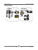
Operator's Manual Fifth Edition • Third Printing Transport and Lifting Instructions Loading the Machine With a Crane Use the lifting eye mounted on the rear mast column. Make sure the mast is fully lowered. Observe and Obey: Only qualified riggers should rig and lift the machine. Only qualified forklift operators should lift the Inspect the entire machine and remove any loose or unsecured items. Always place the lifting hook through the lifting eye so that it points away from the machine.
Fifth Edition • Third Printing Operator's Manual Transport and Lifting Instructions Securing to Truck or Trailer for Transit Always use the extension deck lock when the machine is transported. Turn the key switch to the off position and remove the key before transporting. Use the tie-down points on the chassis for anchoring down to the transport surface. Use chains or straps of ample load capacity. Use a minimum of 4 chains or straps. Adjust the rigging to prevent damage to the chains.
Operator's Manual Fifth Edition • Third Printing Maintenance Maintenance Check the Hydraulic Oil Level Observe and Obey: Only routine maintenance items specified in this manual shall be performed by the operator. Scheduled maintenance inspections shall be completed by qualified service technicians, according to the manufacturer’s specifications and the requirements specified in the responsibilities manual. Maintaining the hydraulic oil at the proper level is essential to machine operation.
Fifth Edition • Third Printing Operator's Manual Maintenance Check the Batteries Scheduled Maintenance Proper battery condition is essential to good machine performance and operational safety. Improper fluid levels or damaged cables and connections can result in component damage and hazardous conditions. Note: This procedure does not need to be performed on machines with sealed or maintenance-free batteries.
Operator's Manual Fifth Edition • Third Printing Specifications Specifications Model GR-12 Airborne noise emissions Height, working maximum 17 ft 4 in 5.3 m Sound pressure level at ground workstation <70 dBA Height, platform maximum 11 ft 4 in 3.5 m Sound pressure level at platform workstation <70 dBA Height, stowed maximum 62 in 1.57 cm Vibration value does not exceed 2 2.5 m/s Height, stowed maximum, standard platform with work station tray 64 in 1.
Fifth Edition • Third Printing Operator's Manual Specifications Model GR-15 Height, working maximum 20 ft 7 in 6.3 m Height, platform maximum 14 ft 8 in 4.5 m Height, stowed maximum 62 in 1.57 cm Height, stowed maximum, standard platform with work station tray 64 in 1.
Operator's Manual Fifth Edition • Third Printing Specifications Model GR-20 Height, working maximum 25 ft 9 in 7.9 m Height, platform maximum 19 ft 9 in 6.1 m 78 in 1.98 cm 31.5 in 80 cm 53 in 1.35 cm 73.3 in 1.86 m Height, stowed maximum Width Length, stowed Length, platform extended (option) Airborne noise emissions Sound pressure level at ground workstation <70 dBA Sound pressure level at platform workstation <70 dBA 2 Vibration value does not exceed 2.
Distributed By: www.genielift.