
User's Manual
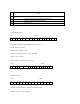

LSB 0 0 9 MSB
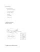
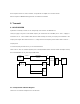
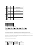
3) Option Control
T CP CP1
CP2
SB1
CP1
CP2
SB2
SBR
LD1
LD2
SW 0 0
T : Test Mode (always "0")
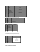
CP : Charge pump output polarity
CP Output Polarity
0 Normal
1 Reverse
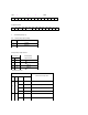
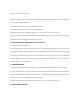
Charge Pump Output Current
Lock detector output
Control bit
SB1 SB2
LD1 LD2
Lock detector output state
0 0 L
0 1 CH2 only detector
1 0 CH1 only detector
0 0
1 1 CH1, CH2
0 0 L
0 1 H
0
0
0
0
0
0
0
0
1
0
0
1
1
1
Control bit
CP1
CP2
Charge pump
output current
0 0
100 µA
0 1
200 µA
1 0
400 µA
0 0
800 µA