
User's Manual


Low Pass Filter eliminate needless spurious and is consist of 2 steps.
3. Receive
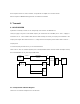
3.1 FRONT-END
Front-end choose and amplify bandwidth of RF signal. Front end is consist of filter and LNA (Low Noise Amp). LNA is
consist of two Transistors (Q10, Q11) and amplify about 20dB. Filter use two SAW Filter (F9. F10) to remain bandwidth
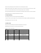
of 450~470MHz. When P0.1 is high, TR Q4 turn on, Band Switching Diode (D18, D19) turn off, F9 turn off and F10 turn
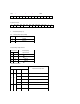
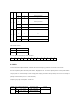
on. Band Width of SAW Filter, as below.
3.2 Mixer
Mixer (Q12) mix received RF signal and local
signal from synthesizer and then generate
21.4MHz, IF frequency. Volume of local signal
is -4dBm at maximum and Conversion Gain about 2dBm.
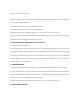
Medium frequency is determined, as below.
F
IF
= F
RF
± F
LOCAL
For preventing spurious. n-Channel Dual Gate MOS-FET, BF998 is used and spurious level of Local and RX RF is less
than -70dB
m.
3.3 Crystal filter and IF AMP
Pass Band Width of 21.4MHz X-TAL filter(F11) is ±6KHz and can use 12.5KHz and 25KHz Spec of MCF : Ripple -
1dB, Insertion Loss - 3dB, MCF reduce about -35dB far from ±20KHz.
IF AMP(Q13) amplify X-TAL filter in 21.4MHz as 25dB. Consumption of voltage is less than 5mA.
3.4 IF IC
IF IC (U11) is consist of second Mixer, Ceramic Filter, 455KHz Resonator, Noise Squelch and SRRI.
Second Mixer generate 455KHz, mixing IF 21.4MHz and 2nd Local 20.945MHz(X10). This signal catches the Ceramic
Filter (F13, F14) with 12.5/25KHz switch (D12, D13) and determines adjacent channel fitting with 12.5/25KHz.
Channel selection in 12.5/25KHz is operated by MPU (U13) P0.4.
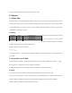
SAW Filter P0.1 frequency range
F9 Low 460~470 MHz
F10 High 450~460 MHz