
Manual


12
Wire The Controls
Two pigtail wires are provided inside the
electrical compartment of the humidifier. This
“AB” to “AB” circuit is the low-voltage control
for the humidistat and air pressure switch.
The humidifier will run when the AB-AB
Circuit is completed.
24 volt A.C. to power the E1 Humidistat may
be pulled from the “G” and “GND” terminals.
The AB-AB circuit is completed through the
12500 Pressure Switch (“NO”, “C” terminals)
and the E1 Humidistat (“OUT” terminals).
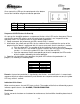
If it is desired for the humidifier to activate the
heating fan during a call for humidity use the
second wiring scheme below.
terminal function electrical specifications
+VR
SET
Enabling jumper external N/O contact; R
max
=50 ; V
max
=10Vdc; I
max
=1mAdc
AB
AB
Input from humidistat remote
enabling input
external N/O contact; R
max
=50 ; V
max
=24Vdc; I
max
=10mAdc
G
GND
24V AC power supply for E1
Humidistat and relay
Output V
max
=24Vac; LOAD
max
=500mA ac