
Operating Guide

(1) Remove power from the circuit to be tested and discharge all high-voltage
capacitors.
(2) Turn the rotary switch to the , or position,, depending on the
amplitude of the current you expect to encounter. If you are unsure of the
amplitude, select the 10A position first and then switch to the or
position if all of your measurements are less than 400mA.
(3) By default, the DMM is initially configured to measure DC rather than AC
current, indicated by the presence of the icon at the lower left of the
LCD. If you are certain that the current you want to measure is DC current,
proceed to Step (4).
If you know that the current you want to measure is AC current, press the
FUNC button once; this will cause the icon to replace the icon on the
left side of the LCD. If you are unsure whether the voltage to be tested is AC
or DC, configure the DMM to measure AC voltage for safety reasons.
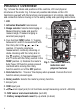
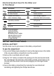
(4) Plug the black test lead into the black COM jack at the bottom left of the
front panel.
(5) Plug the red test lead into the A or jack. Choose the A jack if you
have set the rotary switch to the position, and the jack if you have
set it to the or position.
(6) Break the circuit and touch the red lead to the higher-voltage side of the
break and the black lead to the lower-voltage side.
(7) Re-apply power to the circuit and observe the display. If you are working in
Manual Ranging mode and the display shows O.L, the current amplitude is
beyond the selected current range. If that is the case, use the FUNC button
to select the next-widest position. If the readout is a negative value, the
leads are reversed but the absolute value represents a valid measurement
of current amplitude.
(8) Remove power from the circuit and discharge all high-voltage capacitors.
(9) Remove the test leads and restore the circuit to its original condition by
eliminating the break you made in Step 6.
A
mA
µA
mA
µA
A
C
DC
DC
TEMP
mAµAVΩ
TEMP
mAµAVΩ
mA
µA
A
10