
Use and Care Guide
OPERATING INSTRUCTIONS
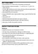
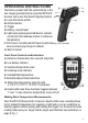
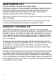
Familiarize yourself with the nomenclature in the
two images provided before using the IRTC50 IR
Scanner with Laser Star Burst Targeting System.
A.
Laser Star Burst pointer
B.
Infrared sensor
C.
Trigger
D.
Battery compartment
E.
Light panel (glows green/red/blue to indicate
normal/hot/cold readings relative to reference
temperature)
F.
Front panel, including backlit liquid crystal display (LCD) screen
(see accompanying image for details)
G.
Built-in buzzer
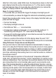
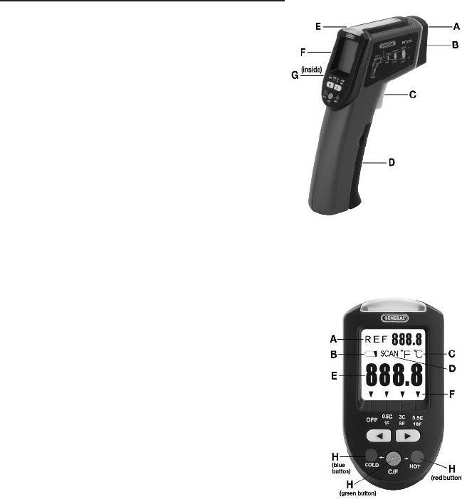
Front Panel Controls and Indicators
A.
Reference temperature (for use with setpoints)
B.
Low battery indicator
C.
Selected temperature scale
D.
Scanning mode indicator
E.
Scanned/held temperature
F.
Selected setpoint band indicators
G.
Differential temperature setpoint band
(1°F/0.5°C, 5°F/3°C, 10°F/5.5°C) selectors
H.
Green button has three functions: toggles between
°F and °C, sets reference temperature, turns unit off
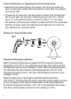
Making Basic Temperature Measurements
Point the IRTC50 thermometer at various objects within view, including those
not at ambient temperature (for example, a light bulb or an air-conditioner or
heating register) while pressing and holding the trigger. For the most accurate
reading make sure your target fills the target spot diameter see illustration on
page 8 Fig. 1.
5