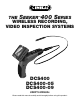
THE SEEKER 400 SERIES WIRELESS RECORDING, VIDEO INSPECTION SYSTEMS TM DCS400 DCS400-05 DCS400-09 User’s ManUal Please read this manual carefully and thoroughly before using this product.
CONTENTS Introduction . . . . . . . . . . . . . . . . . . . . . . . . . . . . . . . . . . . . 3 Overview. . . . . . . . . . . . . . . . . . . . . . . . . . . . . . . . . . . . . . . 3 Features . . . . . . . . . . . . . . . . . . . . . . . . . . . . . . . . . . . . . . . 4 System Includes . . . . . . . . . . . . . . . . . . . . . . . . . . . . . . . . 4 Specifications . . . . . . . . . . . . . . . . . . . . . . . . . . . . . . . . . . 5 Safety and Maintenance Instructions . . . . . . . . . . . .
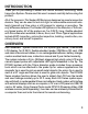
INTRODUCTION Thank you for purchasing a Seeker™400 Series Wireless, Recording, Video Inspection System. Please read this user’s manual carefully before using this product. All of the scopes in The Seeker 400 Series are designed as remote inspection devices. They can be used to look into tight or inaccessible areas and wirelessly transmit real time video or still images for viewing or recording. The only difference between The Seeker 400 systems is the diameter of the camera tipped probe.
FEATURES • 1m (3.28 ft.) long, flexible-obedient probe which is water/dust proof to IP67 standards • 3.5 in. (88.9mm) diagonal TFT-LCD wireless color monitor can be detached from the unit for remote viewing up to 10m (32 ft.) away. Imbedded magnets and flip-out stand on the back of the monitor allow hands-free operation. • 180° image flip feature • 4x zoom feature • Both monitor and handle use rechargeable Li-ion batteries which can be charged at the same time using the included one–into-two charging cable.
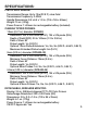
SPECIFICATIONS: PISTOL GRIP HANDLE: Transmission Range: Up to 10m (32.8 ft.) clear field Transmission Frequency: 2.4GHz Handle Dimensions: 8.5 x 6.5 x 1.9 in. (215 x 165 x 50mm) Weight: 15 oz. (425g) Power Source: 1 Lithium-Ion rechargeable battery (included) CAMERA TIPPED PROBES: 12mm (0.47 in.) diameter (DCS400) Resolution: 320 x 240 Pixels (NTSC), 704 x 576 pixels (PAL) Depth of Field (DOF): 30 to 100mm (1.2 to 3.94 in.) Field of View: 60° Probe Length: 1m (3.28 ft.
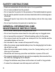
SAFETY INSTRUCTIONS • Read and understand all instructions prior to any operation. • Do not remove labels from the product. • Do not operate the product in the presence of flammable/explosive gases. • Do not use the product around corrosive chemicals which can damage sensitive tips. • Never spill liquid of any kind on the video display units as this may cause damage. • Do not use the device for personal or medical use.
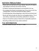
BATTERY PRECAUTIONS • Please use the included factory AC power adapter. Using other AC adaptors may damage the instrument and void the warranty. • Full battery charging and discharging is recommended on first use • The charging time should not be greater than 12 hours for the first few charging cycles. This process will maximize battery capacity. • The discharging time will vary depending on which functions are being used. • Monitor and camera handle use Lithium-Ion rechargeable batteries.
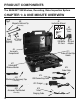
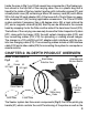
PRODUCT COMPONENTS The SEEKER™400 Wireless, Recording, Video Inspection System CHAPTER 1: A ONE MINUTE OVERVIEW Fig.
Inside the case in Fig.1 you’ll find several key components of the Seeker system stored in the top half of the carrying case. One is a plastic bag that is taped to the inside of the top. Inside it are the unit’s instruction manual (#1) and a small plastic case (#2) containing a Micro SD memory card (#3) and a Micro SD to full size SD card adapter (#4). At the lower left of the lid there is a separate compartment (#5) housing applicable accessories.
LED brightness. Attached to the handle is the 1 meter long probe (#2) which contains the camera (#3) and the LED lights (#4) in the leading end under the black rubber protective cover (#5). Finally there’s the removable and wireless LCD monitor (#6) which controls all of the scope’s functioning and recording controls. The LCD monitor can be attached to the handle or removed and used wirelessly. MAIN CONTROLS The main controls (Fig.
SETTING-UP THE SYSTEM Remove the pistol grip handle with attached probe from the #3 Locking Buckle Clip #1 hard case. Then reConnector move the wireless LCD Slots monitor. Attach the #2 monitor to the handle Dual by aligning the signal Tabs connector slots (#1) on the monitor with the Fig.4 dual tabs (#2) on the top of the handle (Fig.4). Slide the moniSlide tor to the left until it securely engages the locking buckle clip (#3).
CHARGING THE SYSTEM Fig.7 #4 Bi‐Colored Charging Light on Monitor #3 Charging Port on Monitor Slide Monitor to the right to remove from handle #2 Bi‐Colored Charging Light on Handle #2 Bi‐Colored Charging Light on Handle #1 Charging Port on Handle Charging Cables Attached to Handle and Monitor Both the LCD display and the pistol-grip handle have internal Lithium ion rechargeable batteries which can be charged separately or at the same time. (Fig.
PROBE Each SEEKER 400 Video Inspection System is supplied already connected to a one-meter-long flexible-obedient probe. The SEEKER 400 System has a slim 12-millimeter diameter tip. The SEEKER 400-09 system is supplied with an ultra-slim 9-millimeter diameter probe and the SEEKER 400-05 system is supplied with an superslim 5.5-millimeter diameter probe. Whichever SEEKER 400 system you’re using the other probes are available options and are interchangeable with the base unit.
The right side of the LCD monitor (Fig.10) houses the controls and connections you will use to view, record and upload your images as well as charge the unit (Fig.7). To start with, the button on the top right of the unit (#1) performs two functions. When it is pushed and held for 3+ seconds, it turns the display ON and OFF. When it is pressed only briefly (after the unit has been powered up), it toggles the unit’s operating mode between live viewing and recording with playback of pictures and videos. Fig.
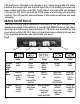
MAIN MENUS MODE Pressing the center “MENU” button (#6) will bring you to a series of menus (Fig.11) used to set-up the system. These include: the Advanced Settings Menu, the Auto Capture Menu and the Time/Date Menu. You can scroll right and left to these 3 menus by using the right and left black arrow buttons (#9, #10). Within each top level menu are sub menus and you can scroll up and down within all of these menus using the two yellow buttons (#7, #8).
PLAYBACK MODE Once you are in the playback mode (after briefly pressing the ON/OFF button on the top of the monitor), the controls have the following functions: 1. Pressing the left or right outer black buttons (#9 or #10) scrolls through your set of stored pictures and video one step either left or right in their order of capture. 2. Pressing the left yellow button (#7) when Fig.12 a projector icon is on-screen controls the playing of that particular video. 3.
CHAPTER 3: TAKING AND VIEWING PICTURES AND VIDEOS Before you are able to take any pictures, make sure that the handle grip and display units are both charged, turned on and that the micro SD memory card is securely plugged into the slot on the right of the display. Make sure that the gold contacts are facing front and inserted first. When the memory card is present, the X will no longer appear over the blue SD icon in the upper left corner of the display (Fig.15).
by pressing the left yellow button. When videos are being played back, a white film strip icon appears in the upper left of the display, next to the timer (Fig.20). To pause or resume playback again press the yellow button with the up arrow. Pressing the yellow button on the right with the down arrow will cancel the play- Fig.18 back and bring you back to the main menu. To return back to live camera mode again briefly press the on/off button.
a USB port of your computer. Once both plugs have been inserted, the DCS400 monitor’s screen will go all blue, except for the letters “MSDC” in the center. Once this has occurred, you can access the stored files through the normal functioning of your computer. The DCS400 will appear as a remote storage device in your computer’s menu. To just view your pictures on a remote device you use the video cable.
CHAPTER 5: THE MENU STRUCTURE SET TIME/DATE ADVANCED SETTINGS AUTO CAPTURE PLAYBACK MENU Auto Capture Set Time/Date Tuner Channel File Delete On YYYY/MM/DD Ch1 Single Off HH:MM:SS Ch2 Delete Exit YY/MM/DD Ch3 Yes Ch4 No Manual Capture Photo Time Stamp Exit All Photo 1 On Photo Quality Photo 3 Off Delete Movie 5 Exit High Quality Yes Movie 10 Standard Quality No Movie Time Stamp Exit Low Quality Cancel On Exit File Overwrite Set Format Off Movie Quality Exit On Yes Off QVGA No Load Default Exit D1 EXIT Yes E
TROUBLE SHOOTING Problems Causes Adapter didn’t make a good connection with Will not product. charge The connector or cable is broken. Dead battery 1. Different channel The screen is set between the on but without grip and screen. image or shows 2. The probe is loose. “No Signal” 3. Stains on the camera head. LEDs on the camera head are dim at max brightness, display changes from black to white, color display turns itself off after a period. The product won’t turn on. Abnormal display or invalid keys.
WARRANTY INFORMATION THREE YEAR LIMITED WARRANTY General Tools & Instruments (General) DCS400 Wireless, Recording, Video Inspection System is warranted to the original purchaser to be free from defects in material and workmanship. Subject to certain restrictions, General will repair or replace this instrument, if after examination, it is determined by General to be defective in material or workmanship for a period of three years.
NOTES ________________________________________________________________________ ________________________________________________________________________ ________________________________________________________________________ ________________________________________________________________________ ________________________________________________________________________ ________________________________________________________________________ ____________________________________________________________________
GENERAL TOOLS & INSTRUMENTS 80 White Street • New York, NY 10013-3567 PHONE (212) 431-6100 • FAX (212) 431-6499 • TOLL FREE (800) 697-8665 e-mail: sales@generaltools.com www.generaltools.com DCS400 User’s Manual Specifications subject to change without notice NOTICE - NOT RESPONSIBLE FOR TYPOGRAPHICAL ERRORS.