DCS200-300 MANUAL 071609 FINAL:Manual 7/16/09 1:25 PM Page 1 DCS200/DCS300 USER’S MANUAL THE SEEKER 200 & THE SEEKER 300 VIDEO INSPECTION SYSTEMS Please read this manual carefully and thoroughly before using this product.
DCS200-300 MANUAL 071609 FINAL:Manual 7/16/09 1:25 PM Page 2 CONTENTS Introduction . . . . . . . . . . . . . . . . . . . . . . . . . . . . . . . . . . . . 3 Features . . . . . . . . . . . . . . . . . . . . . . . . . . . . . . . . . . . . . . . 3 Safety Instructions . . . . . . . . . . . . . . . . . . . . . . . . . . . . . 4 Product Components . . . . . . . . . . . . . . . . . . . . . . . . . . . 5 Installation . . . . . . . . . . . . . . . . . . . . . . . . . . . . . . . . . . . . .
DCS200-300 MANUAL 071609 FINAL:Manual 7/16/09 1:25 PM Page 3 INTRODUCTION The Seeker 200 and The Seeker 300 inspection systems have been designed as a user friendly and economical way of solving hidden problems and increasing productivity. The product has a high clarity color LCD to show clear images. The camera head is housed inside the tip of the probe with adjustable LED lights, which helps you to reach into gaps and holes. The mirror tip is included to make it possible to view different angles.
DCS200-300 MANUAL 071609 FINAL:Manual 7/16/09 1:25 PM Page 4 SAFETY INSTRUCTIONS Failure to follow the instructions listed below may result in electric shock or personal injury. • Read and understand all instructions prior to any operation. • Do not remove any labels from the product. dark areas may cause accidents. • Do not operate the product in the presence of flammable/explosive gases. • Do not use the product around corrosive chemicals which can ruin the picture quality.
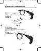
DCS200-300 MANUAL 071609 FINAL:Manual 7/16/09 1:25 PM Page 5 PRODUCT COMPONENTS 1. Hand Held Display Unit 2. Camera Head and Probe 3. Magnetic Tip 4. Hook Tip 5. Mirror Tip A. LCD Screen B. Battery Compartment C. Switch / LED Lighting Adjusting Button D. Probe Connector E. Probe F.
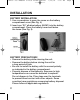
DCS200-300 MANUAL 071609 FINAL:Manual 7/16/09 1:25 PM INSTALLATION BATTERY INSTALLATION: 1. Use a screwdriver to open the screw on the battery compartment cover (See Fig. 4). 2. Insert one “9V” alkaline battery (6LR61) into the battery compartment. Close the battery cover and fasten the screw (See Fig. 5). BATTERY PRECAUTIONS! • Remove the battery while cleaning the unit. • Remove the battery before storing the unit for a long period of time.
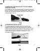
DCS200-300 MANUAL 071609 FINAL:Manual 7/16/09 1:25 PM Page 7 CONNECTING THE DISPLAY UNIT TO THE CAMERA HEAD AND PROBE: The display unit must be connected to the cameral head and probe. To connect the probe to the display unit, make sure the keyed ends are properly aligned (See Fig. 6). Once they are aligned, tighten the nut. ACCESSORIES INSTALLATION: The three accessories include mirror tip, hook tip and magnetic tip (See Fig. 2). All are attached to the camera head the same way.
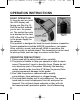
DCS200-300 MANUAL 071609 FINAL:Manual 7/16/09 1:25 PM Page 8 OPERATION INSTRUCTIONS BASIC OPERATION: To turn the unit on, hold the LCD display unit facing you (See Fig. 9). Roll the switch towards you to turn the power on. The switch then acts as a dimmer for the twin LED’s (See Fig.10), which is the power supply for the camera. This product is designed for hard-to-reach distance inspection. Typical applications include HVAC/R inspections, car inspections, circuitry, vessel, and aircraft.
DCS200-300 MANUAL 071609 FINAL:Manual 7/16/09 1:25 PM Page 9 the camera head into corrosive, oily places or high temperature objects. 5. Don’t place the cameral head or probe into anything or anywhere that may contain a live electrical charge. Please check following methods to avoid injury. For walls: For inspecting the inside walls, be sure to shut off the circuit breaker to the whole house before using the tool.
DCS200-300 MANUAL 071609 FINAL:Manual • • • • 7/16/09 1:25 PM Page 10 is dropped, check for the breakage which may affect it’s operation. If it is damaged, have the product serviced before using. Many accidents are caused by poorly maintained products. Use only accessories that are recommended by the manufacturer for your product. Accessories are suitable for the product, but may become hazardous when used on another product.
DCS200-300 MANUAL 071609 FINAL:Manual 7/16/09 1:25 PM Page 11 • Upon completion of any service or repair, please ask the service technician to check if the product is in proper working condition. • Stop using the unit if it starts smoking or emitting noxious fumes. • Remove the battery and ask a qualified personnel under the following conditions: A. If liquid has been spilled or objects have fallen into the product. B.
DCS200-300 MANUAL 071609 FINAL:Manual 7/16/09 1:25 PM Page 12 SPECIFICATIONS Video Inspection Recommended use Viewable Angle Viewable Distance Diameter of Camera Head DCS200 Image Display DCS300 Resolution Accessories Probe Length Light Source Power Source Estimated Battery Life Operating Temperature Operating Humidity Storage Temperature DCS200 Specifications Indoor 60° .98" to 11.8" (2.5 to 30cm) .47" (12mm) 2.4" TFT/LCD 3.5" TFT/LCD 320 x 234 pixels Mirror tip, Hook tip and Magnetic tip 39.
DCS200-300 MANUAL 071609 FINAL:Manual 7/16/09 1:25 PM Page 13 CAUTIONS! • • • • Don’t drop the product or use by force. Don’t disassemble the product to avoid failure. Don’t place the product with corrosive gas or objects. Don’t expose the product in environment which is with shock, too high or too low temperatures. • Store the product in a safe area. • Don’t immerse the product into water which can cause damages to the product. • Please take out the battery if not in use for long period of time.
DCS200-300 MANUAL 071609 FINAL:Manual NOTES 7/16/09 1:25 PM Page 14
DCS200-300 MANUAL 071609 FINAL:Manual NOTES 7/16/09 1:25 PM Page 15
DCS200-300 MANUAL 071609 FINAL:Manual 7/16/09 1:25 PM GENERAL TOOLS & INSTRUMENTS™ 80 White Street New York, NY 10013-3567 PHONE (212) 431-6100 FAX (212) 431-6499 TOLL FREE (800) 697-8665 e-mail: sales@generaltools.com www.generaltools.com DCS200/DCS300 User’s Manual Specifications subject to change without notice ©2009 GENERAL TOOLS & INSTRUMENTS™ NOTICE - WE ARE NOT RESPONSIBLE FOR TYPOGRAPHICAL ERRORS.