NON-CONTACT VOLTAGE DETECTOR WITH ADJUSTABLE SENSITIVITY AND IR THERMOMETER USER’S MANUAL VR40 Please read this manual carefully and thoroughly before using this product.
TABLE OF CONTENTS Introduction . . . . . . . . . . . . . . . . . . . . . . . . . 3 – 6 Key Features . . . . . . . . . . . . . . . . . . . . . . . . . . . 6 Safety Instructions . . . . . . . . . . . . . . . . . . . . 7 – 9 What’s in the Blister Pack . . . . . . . . . . . . . . . . 10 Product Overview . . . . . . . . . . . . . . . . . . . 10 – 12 Setup Instructions . . . . . . . . . . . . . . . . . . . . . . 13 Install Batteries. . . . . . . . . . . . . . . . . . . . . . . 13 Operating Instructions . . . . .
INTRODUCTION Thank you for purchasing General Tools & Instruments’ (General’s) VR40 Non-contact Voltage Detector with Adjustable Sensitivity and IR Thermometer. Please read this manual carefully and thoroughly before using the instrument. The VR40 offers a safe (non-contact) way to check whether a line, cable or AC outlet is “hot” (energized). It does so by using a blade tip to sense from a short distance the electromagnetic field created by AC voltage.
Unlike other NCV detectors with only one sensitivity level—and therefore the ability to detect only one range of voltages (typically 50 to 600VAC)—General’s VR40 has four sensitivity levels. They were chosen to optimize voltage detection over four practical ranges: 12 to 25VAC, 70 to 125VAC, 150 to 240VAC and 250 to 600VAC.
Merely detecting the presence of 120VAC near a bundle of wires does not tell you which wire of the bundle is the “hot” wire; any of the wires could be activating the alarms. The VR40 can help you isolate the hot wire. This application calls for turning down the sensitivity in stages after the NCV detector senses voltage. As you reduce sensitivity, at some stage only the energized wire will produce a field strong enough to activate the NCV’s alarms.
• A unique, patent-pending ergonomic design that places the IR and NCV sensors and the flashlight on the same end of the instrument.
SAFETY INSTRUCTIONS • WARNING • • You must confirm that the batteries powering the VR40 are not weak or dead before you use the unit to test for the presence of AC voltage. It is essential that you do this each time you use the instrument. The usual way to check the batteries is to insert the blade tip into both slots of an outlet known to be energized; if the beeper does not sound and the LED does not light for either slot, replace both “AAA” batteries before proceeding.
• Physically separate the multiple lines of 2-phase and 3-phase circuits before testing them. • Do not use the VR40 if it appears to be damaged or malfunctioning. • Do not expose the tester to temperatures above 113°F (45°C), relative humidity greater than 95%, or voltages higher than 600V. • Do not use the VR40 to test for the presence of DC voltage. • Do not use the unit to test for the presence of AC voltage on a shielded conductor, behind a wall or conduit, or under soil.
The VR40 is a Class 2 laser product that emits less than 1mW of radiation at a wavelength between 630 and 650nm. Avoid looking directly at the laser pointer. U.S. law prohibits pointing a laser beam at aircraft; doing so is punishable by a fine of up to $10,000 and imprisonment. • The laser may cause discomfort if viewed directly. Your eyes’ natural aversion reflex will prevent you from looking at the beam long enough to cause harm.
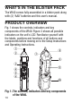
WHAT’S IN THE BLISTER PACK The VR40 comes fully assembled in a blister pack along with (2) “AAA” batteries and this user’s manual. PRODUCT OVERVIEW Fig. 1 shows the controls, indicators and key components of the VR40. Figure 2 shows all possible indicators on the unit’s LCD. Familiarize yourself with the labels, positions and functions of all buttons and components before moving on to the Setup Instructions and Operating Instructions. q w u i o e r t y s a Fig. 1.
1 Non-contact voltage (NCV) detection blade tip 2 NCV detection LED (glows red) 3 LCD 4 Two-function IRT button: 1) Pressed by itself (briefly or held), activates IR thermometer and laser pointer, producing a temperature readout. When button is released, readout is held for 20 seconds, until APO function activates. 2) With NCV button pressed and held, each press of IRT button reduces sensitivity of NCV detector by one level.
9 Infrared sensor 10 Battery compartment 11 Pocket clip Fig. 2. All possible display indications.
SETUP INSTRUCTIONS INSTALL BATTERIES The VR40’s battery compartment (Fig. 1, Callout 10) is accessible from the back of the unit. To open the compartment, place your thumbnail in the slot above the word OPEN and apply enough force to release the battery compartment cover. Slide the cover down and away from the instrument. Insert the two supplied “AAA” batteries in the well using the and markings stenciled inside the compartment as an orientation guide.
batteries are charged, the beeper will sound repeatedly and the red LED under the translucent cap (Fig. 1, Callout 2) will flash when the tip is in one of the slots. Alternatively, briskly rub the tip of the VR40 through your hair or against your skin; static electricity has more than enough voltage to activate the beeper and LED. Whenever the NCV detection circuit is active, the icon will appear on the top line of the LCD.
The figure below also shows which slots of two other common 110VAC receptacles are hot. In both cases, the “hot” slot is on the right and smaller. 2. If the beeper sounds and the LED flashes when the tip is in the larger (left) slot of a modern 15A outlet, the outlet is energized but wired in reverse. 3. If the beeper does not sound and the LED does not light when the tip is in either slot, the circuit is de-energized.
To detect the presence of AC voltage on an individual line or cable, position the blade tip within 1/4 inch of the line or cable and press and hold the NCV button. If the beeper sounds and the LED lights, the line or cable is “hot” (energized). If you do not get both positive indications, touch the tip to all four sides of the line or cable. If the beeper sounds and the LED lights, the line or cable is “hot” (energized). If you still do not get positive indications, the line or cable is deenergized.
measured temperature will be displayed on the LCD, along with the icon on the top line. When you make temperature measurements, be sure to get close enough to the target to ensure that you are reading its temperature alone, rather than the average temperature of the target and objects behind or near it within the IRT’s field of view. The IRT in the VR40 has a distance-to-spot (D:S) ratio of 4:1.
D:S=4:1 To eliminate measurement error, the VR40 must be moved close enough to the target so it is the only object in the target area. The figure below illustrates measurement of a motor’s temperature from the wrong (top) and right (bottom) distance. For a motor with an area of 1 ft2, the optimum measurement distance for the 4:1 IRT in the VR40 would be 4 ft.
To change the temperature unit, press the NCV and IRT buttons at the same time. Each simultaneous press will toggle the unit between °C and °F. The selected unit will appear on the display to the right of the measured IR temperature value. The last temperature unit selected will be recalled the next time the VR40 is activated. To temperature-scan the surfaces of a room or any environment, press and hold the IRT button as you aim the laser pointer in various directions.
Measurement Accuracy: ±3°F (2°C) or ±1% of reading (whichever is greater) above 32°F; ±4.5°F (2.5°C) below 32°F IRT Emissivity: Fixed at 0.95 IR Sensor Spectral Range: 8 to 14μm Display Size and Type: 5/8 in. (16mm) diagonal LCD Display Digits/Counts/Resolution: 4/ 2000/0.
• If the temperature of the IRT’s target is lower than -4°F (-20°C)—the lower limit of the unit’s measurement range—“LO” will appear on the readout. • If the temperature of the IRT’s target is higher than 626°F (330°C)—the upper limit of the unit’s measurement range—“HI” will appear on the readout. • The IRT cannot make accurate measurements if there is glass or plastic between it and the target. • Clean the lens of the infrared sensor (Fig. 1, Callout 9) often—but never use a solvent.
WARRANTY INFORMATION General Tools & Instruments’ (General’s) VR40 Non-contact Voltage Detector with Adjustable Sensitivity and IR Thermometer is warranted to the original purchaser to be free from defects in material and workmanship for a period of three years. Subject to certain restrictions, General will repair or replace this instrument if, after examination, the company determines it to be defective in material or workmanship.
RETURN FOR REPAIR POLICY Every effort has been made to provide you with a reliable product of superior quality.
GENERAL TOOLS & INSTRUMENTS 80 White Street New York, NY 10013-3567 PHONE (212) 431-6100 FAX (212) 431-6499 TOLL FREE (800) 697-8665 e-mail: sales@generaltools.com www.generaltools.com VR40 User’s Manual Specifications subject to change without notice ©2013 GENERAL TOOLS & INSTRUMENTS NOTICE - WE ARE NOT RESPONSIBLE FOR TYPOGRAPHICAL ERRORS.