HOT WIRE ANEMOMETER Model : +:$ 204HA
TABLE OF CONTENTS 1. FEATURES................................................................ 1 2. SPECIFICATIONS...................................................... 2 2-1 General Specifications......................................... 2 2-2 Electrical Specifications........................................3 3. FRONT PANEL DESCRIPTION.................................... 4 3-1 Display............................................................. 4 3-2 Power Off/On Button......................................
1. FEATURES * Thermal anemometer, available for very low air velocity measurement. * Slim probe, ideal for grilles & diffusers. * Combination of hot wire and standard thermistor, deliver rapid and precise measurements even at low air velocity value. * Microprocessor circuit assures maximum possible accuracy, provides special functions and features. * Super large LCD with dual function meter's display, read the air velocity & temp. at the same time. * Heavy duty & compact housing case.
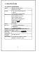
2. SPECIFICATIONS 2-1 General Specifications Circuit Display Measurement Sensor Structure Custom one-chip of microprocessor LSI circuit. * 0.5" (13 mm) Super large LCD display. * Dual function meter's display. m/s (meters per second) km/h (kilometers per hour) ft/min (feet/per minute) knots (nautical miles per hour) mile/h(miles per hour) Temp. F/C 蚓, 蚌. Data hold. Air velocity : Tiny glass bead thermistor. Temperature : Precision thermistor. Memory Maximum and Minimum with recall.
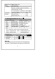
Power Current Approx. DC 30 mA. Weight 0.78 LB (355 g). Dimension Main instrument: 7.1 x 3.1 x 1.5 inch ( 185 x 78 x 38 mm ). Telescope Probe : Round, 0.5"(12 mm)Dia x 11"(280 mm) (min. length). 0.5"(12 mm)Dia x 37"(940 mm) (max. length). Accessories Instruction manual...................... 1 PC. Included Telescope Probe..........................1 PC. Hard carrying case.................... 1 PC. 2-2 Electrical Specifications (23 5 C 蚓) A. Air velocity Measurement Range Resolution Accuracy m/s 0.2-20.
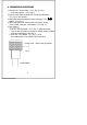
3. FRONT PANEL DESCRIPTION Fig.
4. MEASURING PROCEDURE 1) Connect the " Probe's Plug " (3-13, Fig. 1) to the " Probe Input Socket " (3-10, Fig.1). 2) Power on the meter by push the " Power On/Off Button " (3-2, Fig.1) once a while. 3) Select the desired temperature units, using the " F/C "蚓/蚌 Button (3-4, Fig. 1). 4) Select the desired air velocity units, m/s, km/h, ft/min, knots, mile/h, using the " Unit Button " (3-8, Fig. 1). 5) Zero setting : a. On the " Sensing Head " (3-11, Fig.
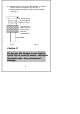
6) a. Slide the sensor cover to the down position, let the air velocity sensor to contact the air, refer Fig. 3. b. Extent the telescope probe to the convenient length, refer Fig. 4 air velocity sensor ( do not touch by fingers or tools ) " Sensor cover " slide to the low position when make the measurement Probe Handle Fig. 3 Fig. 4 Caution !!! Do not use the fingers or any tools to touch the air velocity sensor, otherwise the meter may have permanent damage.
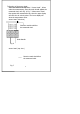
7) Direction of the sensor head : There is a mark on the top of the " Sensor Head ", When make the measurement, then this mark should against the measured wind, refer Fig. 6, Fig. 7. When sensor head face against the measurement air, then the upper display will show the air velocity value. The lower display will show the temperature value. sensor head ( side view ) Direction mark should face the measured wind. Probe Handle Fig. 6 sensor head ( top view ) Direction mark should face the measured wind. Fig.
8) Data Hold : a. During measurement, pushing the " Data Hold Button " (3-3, Fig. 1) will hold the display values & the LCD will show the " D.H " symbol. b. To cancel the Data Hold function, Press the Data Hold Button once more. 9) Data Record ( Max. & Min. reading ) a. The Data Record function displays the maximum & minimum readings. To start the Data Record function, press the " Record Button " (3-5, Fig. 1) once. " REC " symbol will appear on the LCD display. b.
10) For quick measurement, follow the procedures shown below : Main procedures : Power On * Select the 蚓 or 蚌 * Determine the display unit Zero Optional measuring procedures : DATA HOLD MEMORY RECORD Max., Min. 5. BATTERY REPLACEMENT 1) When the left corner of LCD display show " LBT ", it is necessary to replace the battery. However, in-spec measurement may still be made for several hours after low battery indicator appears before the instrument become inaccurate.