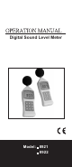
Digital Sound Level Meter Model: 8921 8922
INTRODUCTION Your digital sound level meter provides automatic or manual ranging in six meas-urement ranges from 30 to 130dB. The unit meets ANSI S1.4 and IEC 651 Type 2 standards, and features 0.1dB resolution. A background noise absorber permits you to measure sound levels accurately even in the presence of high background noise. The meter allows you to select between fast and slow response times and A and C weighting. A maximum hold function is provided.
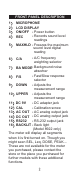
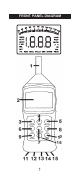
FRONT PANEL DESCRIPTION 1 2 3 4 5 6 7 8 9 MICROPHONE LCD DISPLAY ON/OFF - Power button - Records sound level REC readings MAXHLD - Freezes the maximum sound level digital reading - A/C frequency weighting selector BA MODE Background noise absorber Fast/Slow response F/S selector DOWN - Adjusts the measurement range C/A - Adjusts the measurement range - DC adapter jack 11 DC 9V - Calibration screw 12 CAL 13 AC OUT - AC analog output jack 14 DC OUT - DC analog output jack - RS-232 output jack 15 RS232 16
FRONT PANEL DIAGRAM 0 16
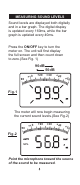
MEASURING SOUND LEVELS Sound levels are displayed both digitally and in a bar graph. The digital display is updated every 160ms, while the bar graph is updated every 40ms. Press the ON/OFF key to turn the meter on. The unit will first display the full screen and then count down to zero.(See Fig. 1) 90dB 50dB 90 +10 +2 0 +30 +40 +5 0 Fig.1 The meter will now begin measuring the current sound levels.(See Fig.2) 50 +10 +2 0 +30 +40 +5 0 Fig.
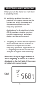
SELECTING A AND C WEIGHTING When you turn the meter on, it will be in A weighting mode. A weighting enables the meter to respond in the same manner as the human ear, which increases and decreases amplitude over the frequency spectrum. Applications for A weighting include OSHA regulatory testing, environmental measurement, workplace design, and law enforcement. C weighting is suitable for flat response measurements with no increase or decrease of amplitude over the frequency spectrum.
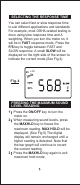
SELECTING THE RESPONSE TIME You can select fast or slow response time to suit different applications and standards. For example, most OSHA-related testing is done using slow response time and A weighting. When you turn the meter on, it will be in FAST response mode. Press the F/S key to toggle between FAST and SLOW response. A small SLOW will be displayed on the right side of the screen to indicate the current mode.(See Fig.4) 40 +10 Fig.
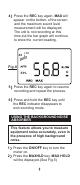
60 FAST Fig.5 A RECORDING THE MAXIMUM AND MINIMUM MEASUREMENTS 1 Press the ON/OFF key to turn the meter on. 2 Press the REC key. REC will be displayed on the bottom of the screen(See Fig.6) . The meter will begin tracking the maximum and minimum sound level measurements. 40 +10 Fig.6 SPL 3 Press the REC key again. MIN will appear on the bottom of the screen (See Fig.7) and the mini. sound level measurement will be displayed.
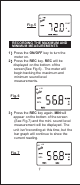
4 Press the REC key again. MAX will appear on the bottom of the screen and the maximum sound level measurement will be displayed. The unit is not recording at this time,but the bar graph will continue to show the current reading. 40 +10 Fig.8 SPL 5 Press the REC key again to resume recording and repeat the process. 6 Press and hold the REC key until the REC indicator disappears to exit recording mode.
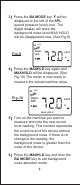
3 Press the BA MODE key. F will be displayed to the left of the SPL (sound pressure level) icon. The digital display will show the background noise level.MAX HOLD will be disappeared now. (See Fig.9) 60 +10 UNDR Fig.9 FAST A 4 Press the MAXHLD key again and MAXHOLD will be displayed. (See Fig.10) The meter is now ready to measure the actual machine noise. 60 Fig.10 +10 UNDR FAST A MAX HOLD 5 Turn on the machine you want to measure and note the new sound level reading.
BACKLIT KEY (8922 only) Offer a light for approximate 5 seconds to make it easier to see the display in the dark. SELECTING AUTOMATIC AND MANUAL RANGING The meter features six measurement ranges in 10dB steps: 30~80dB, 40~90dB, 50~100dB, 60~110dB, 70~120dB, 80~130dB. When you turn the meter on, it will be in automatic range mode and a small AUTO will be displayed on the left side of the screen (See Fig.11) . In this mode, the meter will adjust the measurement range automatically for accuracy.
TO ADJUST THE RANGE MANUALLY: 1 When measuring sound levels,press the DOWN and UPPER keys as needed to adjust the measurement range. MANU will appear on the display (See Fig.12) .Note that the two digit number to the left of the bar graph will change to reflect the low of the newly selected range. If the meter is operating in manual range and UNDR is displayed (See Fig.13) , the sound is too low or the range. If UPER is displayed (See Fig.14) ,the sound is too loud.
To override the Auto Shut Off feature: 1 Make sure the unit is turned off. 2 Press the ON/OFF and MAXHLD buttons simultaneously. 3 When the full display appears, release the MAXHLD button first. "n" will appear on the screen in one second (See Fig.15) , then enter the power on mode ; i.e. count down from: 99.9 88.8 77.7 66.6 55.5 44.4 33.3 22.2 11.1 00.0 and then a current sound level measurement is started. Fig.15 4 Release the ON/OFF key.
SPECIFICATIONS Applicable Standards IEC 651 Type 2, ANSI S1.4 Type 2 Measurement 31.5Hz~8KHz Frequency Range 1.5dB(Under reference Accuracy conditions) Measurement Level A Weighting 30dB~130dB Measurement Level C Weighting 35dB~130dB Measurement Level Range 6 ranges in 10dB steps: 30~80dB, 40~90dB, 50~100dB, 60~110dB, 70~120dB, 80~130dB Automatic Range 30~130dB Time Weighting Fast and slow Segment Range 50dB Digital Display 3 1/2 digit LCD, 0.1dB resolution updated every 0.
RS232 OUTPUT: The meter can link with personal computer to capture on-line datas , display presure records with real-time output, you can retrieve file, save the datas for operating data analysis, records statistic, multi-files display in the screen,....versatile functions for your choice. Connection procedures: 1. Plug the optional accessory RS232 cable onto the DC jack port ( at the right side of the meter) 2. Instert the D-sub 9P type connector onto computer's Com.1 or 2 port or.... 3.
MATERIAL SUPPLIED This standard package contains: 1. The meter x 1 2. Battery x 1 (9.0 volt) 3. Operation manual x 1 4. Buffer x 1 5. Hard Carrying case x 1 Optional accessory: a) RS232 software CD-R. b) D-sub connector.