TABLE OF CONTENTS 1. FEATURES............................................................ 1 2. SPECIFICATIONS................................................... 2 3. FRONT PANEL DESCRIPTION.................................. 5 4. PH CALIBRATING PROCEDURE................................7 4-1 Calibrating Consideration...................................7 4-2 Requiring Equipment for calibration................... 7 4-3 Two Points Calibration...................................... 7 4-4 Singal Point Calibration.
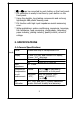
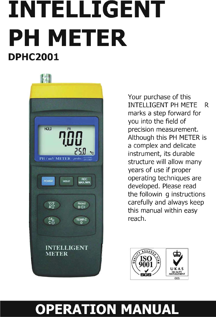
1. FEATURES * Master meter is a professional PH/mV METER. PH range : 0 to 14 PH x 0.01 PH. mV range : -1999 mV to 1999 mV. * DPHC2001 can be plugged with the optional Conductivity and TDS probe, ( YK-200PCT ) Conductivity probe, ( YK-200PCD ) Dissolved Oxygen probe, ( YK-200PDO ) to be a professional Conductivity meter, TDS ( Total Dissolved Solids) meter , or Dissolved Oxygen meter. After plugging in the new probe, no new calibration procedures are required.
* 蚓 or 蚌 can be converted by push button on the front panel. * PH calibration is easily to be done by push button on the front panel. * Using the durable, long-lasting components and a strong lightweight ABS-plastic housing case. * PH function with high input impedance avoids measuring error. * Wide applications: water conditioning, aquariums, beverage, fish hatcheries, food processing, photography, laboratory, paper industry, plating industry, quality control, school & college. 2.
Intelligent functions * The instrument can be plugged with the optional Conductivity and TDS probe (YK-200PCT), Conductivity probe (YK-200PCD), Dissolved Oxygen probe (YK-200PDO) to become a professional Conductivity meter, TDS(Total Dissolved Solids) meter, and Dissolved meter. After plugging in the new probe, no new calibration procedures are required. * The instrument is with mV ( millivolt ) function for mV measurement ( Be plugged with optional ORP probe ORP-04 to be a professional ORP meter).
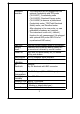
Weight 250 g/0.55 LB ( battery included ). Size ( meter ) 195 x 68 x 30 mm ( 7.6 x 2.6 x 1.2 inch ). Standard Accessories Optional Probes & Accessories Instruction manual...........1 PC. PH electrode, PE-03, PE-01, PE-11 ATC temp.
3. FRONT PANEL DESCRIPTION Fig.
Fig. 2 Fig. 3 3-1 Display 3-2 Power Button 3-3 REC. Button 3-4 Hold Button 3-5 C, F Button/A Button/up Button 3-6 PH/mV Button/B Button/left Button TEMP.
4. PH CALIBRATION PROCEDURE 4-1 Calibration Consideration The most ideal PH ELECTRODE generates 0 mV at PH 7.00 ( 177.4 mV at PH 4 ) and YK-2001PH has been always calibrated with signals which simulate the most ideal PH ELECTRODE ( based on 25蚓 ambient environment ). However not every PH ELECTRODE is as accurate as the most ideal one, so calibration procedures are necessary to be done before the first time measurement.
4) PH 7 calibration Connect the PH ELECTRODE with the " BNC socket " ( 3-10, Fig. 1 ) and immerse the electrode in the PH7 buffer solution. Press the " CAL Button " ( 3-8, Fig. 1 ) then the upper display shows texts of " CAL " and the lower display shows the default calibration value. CAL 7.00 * The texts " CAL " will flash for around 5 seconds. After that, the meter calibrates itself automatically. The upper display will show the calibrated value, the lower display will show the temperature value. 7.
CAL 4.00 * The texts " CAL " will flash for around 5 seconds. After that, the meter calibrate itself automatically. The upper display will show the calibrated value, the lower display will show the temperature value. 4.00 25.0 6) Rinse the electrode with distilled water again. 7) Repeat above (4) to (5) procedures two times at least. 8) The instrument and electrode are now finished the " TWO POINTS CALIBRATION " & ready for the measurement.
4-5 Others Above calibration procedures effect only when reading value within 1 PH of the calibration point. However if the reading value beyonds * 1 PH of PH 7 ( > PH8, < PH6 ) * 1 PH of PH 4 ( > PH5, < PH3 ) * 1 PH of PH 10 ( > PH11, < PH9 ) the calibration procedures are : 1) Connect the PH ELECTRODE to the " PH BNC Input Socket " ( 3-10, Fig. 1 ). 2) Power on the instrument by pressing the " Power Button " ( 3-2, Fig. 1 ). 3) Press the " PH/mV Button " ( 3-6, Fig.
5. PH TEMPERATURE COMPENSATION Enable the meter to gain high accuracy measuring results from different kinds of solution, the temperature compensation calibration procedures are necessary to be executed. Manual temperature compensation calibration procedures please refer to 5-1 ( See below). Automatical temperature compensation calibration procedures please refer to 5-2 ( Page 15 ).
a. Adjust the temperature compensation value * Press the " TEMP. C Button " ( 3-7, Fig. 1 ) first, The upper display will show the measured PH values. the lower display will show the manual temperature compensation value. PH 7.91 026.1 蚓 @ Use the " Left Button " ( 3-6, Fig. 1 ), " Up Button " ( 3-5, Fig. 1 ) and the " Down Button " ( 3-8, Fig. 1 ) to adjust the manual temperature compensation value. b. Adjust the PH 4 default calibration value * When the manual temp. compensation values be adjusted.
@ Use the " Up Button " ( 3-5, Fig. 1 ) and the " Down Button " ( 3-8, Fig. 1 ) to adjust the PH 4 default calibration value. @ The adjustment range of " PH4 default calibration value " is limited within 4.0 0.20 PH c. Adjust the PH 7 default value * When the PH 4 default value be adjusted. Press the " TEMP. C Button " ( 3-7, Fig. 1 ) once again to adjust the PH 7 default calibration value. The upper display will show the values of " 7.
The upper display will show the values of " 10.00 " and the lower display will show the " PH 10 default calibration value ". PH 10.00 10.02 @ Use the " Up Button " ( 3-5, Fig. 1 ) and the " Down Button " ( 3-8, Fig. 1 ) to adjust the PH 10 default calibration value. @ The adjustment range of " PH10 default calibration value " is limited within 10.0 0.20 PH e. Finish the adjustment * When the PH 10 default calibration value be adjusted, press the " TEMP. C Button " ( 3-7, Fig.
5-2 Automatic temperature compensation 1) Plug the " Optional ATC Temp. Probe, YK-200ACT " into the " Optional Probe Input Socket " ( 3-12, Fig. 1 ). Slide the " Lock Switch " ( 3-11, Fig. 1 ) to the lock ( ) position. 2) Power on the instrument by pressing the " Power Button " ( 3-2, Fig. 1 ). 3) Press the " PH/mV Button " ( 3-6, Fig. 1 ) to select the PH function with a "PH" symbol on the display 4) Place the "Temp.
4) * If the operating is under the " Manual temperature compensation ", then please refer to the above 5-1 calibration procedures. * If the operating is under the " Automatic temperature compensation ", then please refer to the above 5-2 calibration procedures. 5) Place the electrode into the solution, then the instrument will have the PH value on the display. 6) After the measurement, please rinse the electrode with distilled water.
6-4 Data Hold Press the " Hold Button " ( 3-4, Fig. 1 ) will hold the measured value & the LCD will indicate a " HOLD " symbol on the display during the measuring. * Press the " Hold Button " again to exit the data hold function. 6-5 Data Record ( Max., Min. reading ) * The data record function records the maximum and minimum readings. Press the " REC. Button " ( 3-3, Fig. 1 ) to start the Data Record function and there will be a " REC " symbol on the display.
6-6 Following are the block diagrams for quick measuring procedures Calibration Power ON Set the manual temp. values Single point calibration PH 7(CAL.) Two points calibration PH 7(CAL.) & PH4 ( PH10, SLOPE) or plug ATC probe PH measuring procedures Power ON Setting the Manual temp. compensation values on front panel or Automatic temperature compensation by optional ATC probe M E A S U R E M E N T Optional measuring procedures DATA HOLD MEMORY RECORD Max., Min.
Power management AUTO POWER OFF (Not activated during MANUAL POWER OFF or Memory Record Selection) 7. DISABLE AUTO POWER OFF The instrument has " Auto Power Off " function in order to prolong battery life. The meter will shut off automatically if none of the buttons are pressed in approx. 10 min. To disable this function, Select the memory record function during the measurement by pressing the " REC. Button " ( 3-3, Fig. 1 ). 8. RS232 PC SERIAL INTERFACE The instrument features RS232 output via 3.
Meter (3.5 mm jack plug) PC (9W 'D" Connector) Center Pin.............................. Pin 4 Pin 2 Ground/shield............................ Pin 2 Pin 5 2.
9. BATTERY REPLACEMENT 1) When the left corner of LCD display show " ", it is necessary to replace the battery. However, in-spec. measurement may still be made for several hours after low battery indicator appears before the instrument become inaccurate. 2) Slide the " Battery Cover " (3-14, Fig. 1) away from the instrument and remove the battery. 3) Replace with 9V battery ( Alkaline or Heavy duty type ) and reinstate the cover. 4) Make sure the battery cover is secured after changing the battery. 10.
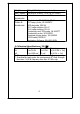
CONDUCTIVITY PROBE Model : YK-200PCD CONDUCTIVITY and TDS PROBE Model : YK-200PCT ORP ELECTRODE Model : ORP-04 BUFFER SOLUTION PH-07 BUFFER SOLUTION PH-04 * YK-200PCD plug into the YK-2001PH to become a professional Conductivity Meter. Measurement Conductivity Conductivity 蚓 蚌 Range 2 mS 20 mS 0 蚓 to 60 蚓 32蚌 to 140 蚌 * YK-200PCT plug into the YK-2001PH to become a professional Conductivity & TDS Meter.
ATC PROBE Model : YK-200PATC * YK-200PATC plug into the YK-2001PH to be a ATC (Automatic Temperature Compensation ) Probe for PH function. Measurement 蚓 蚌 Range 0 蚓 to 65 蚓 32蚌 to 149 蚌 CARRYING CASE CA-06 Hard carrying case PH ELECTRODE PE-03 General purpose, laboratory & field usage. 12.3 mm dia. x 160 mm. Epoxy body, 1 - 13 pH. General purpose, laboratory & field usage. 10 mm dia. x 130 mm. Epoxy body, 1 - 13 pH. (0 - 14 pH typical) Professional, laboratory & field usage. 9.5 mm dia. x 130 mm.