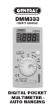
DMM333 USER’S MANUAL DIGITAL POCKET MULTIMETER AUTO RANGING
TABLE OF CONTENTS TITLE PAGE INSTRUMENT..........................3 OVERVIEW FEATURES ...............................4 SPECIFICATIONS....................5-6 SAFETY COMPLIANCE .........7 SAFETY ....................................8-15 INFORMATION ELECTRICAL ...........................16 SYMBOLS OPERATING.............................17-25 INSTRUCTIONS MAINTENANCE ......................
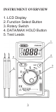
INSTRUMENT OVERVIEW 1. LCD Display 2. Function Select Button 3. Rotary Switch 4. DATA/MAX HOLD Button 5.
FEATURES • Data Hold, Max Hold Ranging • Easy to use • Continuity Beeper, Diode Test • Auto Power Off • Low Battery Indicator • Fast Sampling Rate • Built-In-Test Leads 4
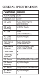
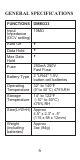
GENERAL SPECIFICATIONS FUNCTIONS DMM333 Auto Ranging auto Display Count 2000 DC Volts Auto 200mV/2/20/ 200/500VDC DC Volts Accuracy ±(0.5%+5dgt) AC Volt Auto 2/20/200/500VAC AC Volts Accuracy ±(0.8%+5dgt) Resistance (Ohms) Auto 200/2k/20k/ 200k/2M/20MΩ Resistance Accuracy ±(0.8%+5dgt)<1MΩ, ±(2%+5dgt)≥1MΩ Diode Test Continuity (audible) • • DC Amps 200µ/2000µA/20m/200mADC DC Amps Accuracy ±(1.8%+5dgt) AC Amps 200µ/2000µA/20m/200mAAC AC Amps Accuracy ±(1.
GENERAL SPECIFICATIONS FUNCTIONS DMM333 10MΩ Input Impedance (DCV setting) Auto Off Data Hold Max Data Hold • • • Fuse 250mA 250V Fast Fuse Battery Type 2 “LR44” 1.5V button cell batteries Operating Temperature 32° to 140°F (0°to 40°C) ≤75%RH Storage Temperature 14° to 122°F (-10° to 50°C) ≤75% RH Size(L×W×H) Approx 4.5" x 2.3" x .
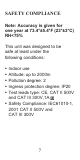
SAFETY COMPLIANCE Note: Accuracy is given for one year at 73.4°±5.
SAFETY INFORMATION To avoid electric shock or injury: • Do not perform the performance tests or adjustment procedures described in this manual unless you are qualified to do so. • The information provided in this manual is for the use of qualified personnel only. • Read “Safety Information” before using this meter. • This multimeter is battery operated, with a digital display. • The Meter complies with IEC61010-1,2001 CATII 500V and CATIII 300V. Refer to “General Specifications” for more information.
SAFETY INFORMATION (continued) • In this manual, a Warning identifies conditions and actions that pose hazards to the user. • A Caution identifies conditions and actions that may damage the Meter or the equipment under test. International symbols used on the Meter and in this manual are explained in Table 1 on page 16.
To avoid possible electric shock or personal injury, and to avoid possible damage to the Meter or to the equipment under test, comply with the following practices: 1. Do not use the Meter in a manner not specified by this manual or the safety features of the Meter may be impaired. 2. Before using the Meter, inspect the case. Do not use the Meter if it is damaged. Look for cracks or missing plastic. Pay particular attention to the insulation around the connectors. 3.
metal. Check the test leads for continuity. Replace damaged test leads before using the Meter. Only test leads meeting CE, CAT II 500V and CAT III 300V 1A can be used in this multimeter. Replacing test leads should be referred to qualified service personnel only. 4. Verify a Meter’s operation by measuring a known voltage. Do not use the Meter if it operates abnormally. Protection may be impaired. When in doubt, have the Meter serviced. 5.
6. Do not measure voltages above 500 V in Category II, or 300 V in Category III installations. 7. Do not measure voltage when the function/range switch is set on the resistance (ohms) or the current (µA/mA) settings. Never measure current when the meter is set on the resistance range. Never measure AC voltage when the meter is set on DC voltage or DC current settings. Setting the meter on the incorrect function may burn out some of the internal circuitry and may pose a safety hazard. 8.
9. Use the proper terminals, function, and range for all measurements. 10. Do not operate the Meter around explosive gas, vapor, or dust. 11. When using the probes, keep the fingers behind the finger guards. Do not touch the metal probes of the test leads when making a measurement. 12.When making connections, connect the common test lead before connecting the live test lead; when disconnecting, disconnect the live test lead before disconnecting the common test lead 13.
capacitors before testing resistance, continuity, diodes, or capacitance. 14.For all DC functions, to avoid the risk of shock due to possible improper reading, verify the presence of any AC voltages by first using the AC function. Then select a DC voltage range equal to or greater than the AC range. 15.Before measuring current, you should turn off power to the circuit before connecting the Meter to circuit. 16.Do not operate the Meter with the case (or part of the case) removed. 17.Use only two 1.
the Meter case, to power the Meter. 18.Replace the battery as soon as the battery indicator “ ” appears. With a low battery, the Meter might produce false readings that can lead to electric shock and personal injury. Don’t replace batteries with the wrong type. Otherwise, you may encounter hazards! 19.Remove test leads from the circuit under test before opening the Meter case. 20.When servicing the Meter, use only specified replacement parts.
TABLE 1. ELECTRICAL SYMBOLS SYMBOL DESCRIPTION AC (Alternating Current) DC (Direct Current) Caution, risk of electric shock Hazardous voltage Battery (Low battery when shown on the display). Diode AC or DC Fuse Double Insulated Risk of danger. Important Information. Refer to the manual.
OPERATING INSTRUCTIONS • Data Hold and Max Hold Press the “H” (Hold) button to hold present reading, and press the “M” (Max Hold) button to hold max reading. • DC Voltage Measurement Do not measure voltage higher than 500V. If the voltage is over 1000 VDC, the beeper will sound for warning continuously, designating an over-range measurement. 1.Set the function/range switch to the appropriate DC voltage range. 2.
3.Read the measured voltage on the display. If the test leads are reversed, the “ — ” indicator will appear on the display.
• AC Voltage Measurement Do not measure voltage higher than 500V. It may make damage to internal circuit. If the voltage is over 750 VAC, the beeper will sound for warning continuously, designating an over-range measurement. 1.Set the function/range switch to the appropriate AC voltage range. 2.Measure the voltage by touching the probes to the desired test points of the circuit. With AC voltage, the polarity of the test leads is not a factor. 3.Read the measured voltage on the display.
• Resistance Measurement (Ω) To avoid electrical shock or damage to the meter when measuring resistance or continuity in a circuit, make sure the power to the circuit is turned off and all capacitors are discharged. 1.Turn the rotary switch to the appropriate resistance (ohms) range. Make sure power is disconnected from the circuit to be measured. 2.Measure the resistance by touching the probes to the desired test points of the circuit. 3.Read the measured resistance on the display.
“OL” will be indicated on LCD display. red test lead black test lead • Diode Check 1.Turn the rotary switch to the diode/continuity position. Diode check is the default setting, switch functions by pushing the YELLOW button. 2.Connect the red probe to the anode side and the black probe to the cathode side of the diode being tested. 3.Read the forward bias voltage value on the display.
4.If the polarity of the test leads is reversed with diode polarity, the display reading shows “OL”. This can be used to distinguish the anode and cathode sides of a diode. 5.For silicon diode, forward bias voltage should be 0.5∼0.8V, for germanium diode, forward bias voltage should be 0.2∼0.3V. A “0 V” reading in both directions indicates a shorted diode. An “OL” reading indicates an open diode. In either case, the diode is defective and should be replaced.
• Continuity Measurement 1.Turn the rotary switch to the diode/continuity position. Diode check is the default setting, switch functions by pushing the YELLOW button. 2.If the resistance is under 50 Ω, the beeper will sound continuously, designating a short circuit. If the meter reads “OL”, the circuit is open. 3.Read the measured resistance on the display. When the resistance value is over range, “OL” will be indicated on LCD display.
• DC /AC Current Measurement (µA/mA) 1.Turn the rotary switch to the current range, if the tested current range is unknown, set it to mA setting first. 2.Toggle between AC or DC current measurement by pressing the YELLOW button. 3.Break the circuit path to be measured. Then connect the test leads across the break and apply power. 4.Read the measured current on the display. 5.
continuously, designating an over-range measurement. red test lead black test lead • Turn Off Please set the function switch to the OFF position after using. The Meter enters the “Sleep mode” and blanks the display if the Meter is not used and the input is inactive for 15 minutes. Press any button to wake the Meter up.
MAINTENANCE If the Meter fails, check the batteries and fuses first, review this manual to make sure that you are operating the Meter correctly. Disconnect test leads before opening the case or the battery door. To avoid false readings, which could lead to possible electric shock or personal injury, replace the batteries as soon as the battery indicator “ ” appears. To prevent damage or injury, install ONLY replacement fuses with the specified amperage, voltage, and interrupt ratings.
NOTES ............................................................ ............................................................ ............................................................ ............................................................ ............................................................ ............................................................ ............................................................ ............................................................ ..................
GENERAL TOOLS & INSTRUMENTS™ 80 White Street New York, NY 10013-3567 PHONE (212) 431-6100 FAX (212) 431-6499 TOLL FREE (800) 697-8665 e-mail: sales@generaltools.com www.generaltools.com DMM333 User’s Manual Specifications subject to change without notice ©2009 GENERAL TOOLS & INSTRUMENTS™ NOTICE - WE ARE NOT RESPONSIBLE FOR TYPOGRAPHICAL ERRORS.