
Instruction Manual
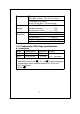
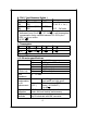
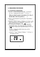

Fig. 1
3-1 Display
3-2 Power Button
3-3 REC. Button
3-4 Hold Button
3-5
A
Button (
蚓
,
蚌
Button )
up Button
3-6 B Button ( Range Button )
PH/mV Button/left Button
3-7 C Button ( CD/TDS Button )
CAL Button/down Button
3-8 D Button ( TEMP. C Button )
3-9 Battery Compartment/Cover
3-10 PH BNC Input Socket
3-11 Lock Switch
3-12 Conductivity/TDS Input Socket
3-13 RS-232 Out Terminal
3-14 Stand
3-15 PH 7 V
R
3-16 PH 4/PH 10 V
R
3-17 Conductivity/TDS Probe
3-18 Conductivity/TDS Probe pLug
6