THE SEEKER™200 SERIES & THE SEEKER™300 SERIES VIDEO INSPECTION SYSTEMS DCS200 (shown) DCS300 (shown) DCS200/DCS200-09/DCS200-05 DCS300/DCS300-09/DCS355 USER’S MANUAL Please read this manual carefully and thoroughly before using this product.
CONTENTS Introduction . . . . . . . . . . . . . . . . . . . . . . . . . . . . . . . . . . . 3 Features . . . . . . . . . . . . . . . . . . . . . . . . . . . . . . . . . . . . . . . 3 Probe Tip Accessories . . . . . . . . . . . . . . . . . . . . . . . . . . 4 Product Overview . . . . . . . . . . . . . . . . . . . . . . . . . . . . . . 4 Battery Installation . . . . . . . . . . . . . . . . . . . . . . . . . . . . . 5 Disconnecting and Reconnecting the Probe . . . . . . . 6 Installing the Accessories . . . . .
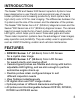
INTRODUCTION The Seeker™200 and Seeker 300 Series Inspection Systems have been designed as a user friendly and economical way of viewing hidden problems and increasing productivity. Each system has a high clarity color LCD for clear imaging. The differences between the 3 systems are the size of the screen and the diameter of the probes. The Seeker™200 Series has a 2.4" (60.9mm) diagonal screen and the Seeker™300 Series has a 3.5" (88.9mm) diagonal screen.
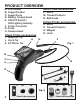
PRODUCT OVERVIEW A. LCD Screen B. Image Rotation C. Image Zoom D. Battery Compartment E. ON/OFF Switch / LED Lighting Intensity F. Probe Connector G. Probe H. Camera Head 5mm Probe accessories L. Mirror M. Thread Protector N. Ball Guide 9.0mm Probe accessories O. P. Q. R. 12mm Probe accessories I. Magnetic Tip J. Hook Tip K. 45º Mirror Tip A Mirror Thread Protector Magnet Hook H F Fig. 1 B C E G 12mm Probe accessories I D J K L M O N P Q R Fig. 2 4 5.5mm Probe accessories 9.
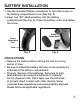
BATTERY INSTALLATION 1. Use the included Phillips screwdriver to open the screw on the battery compartment cover (See Fig. 3). 2. Insert one “9V” alkaline battery into the battery compartment (See Fig. 4). Close the battery cover and fasten the screw. Battery Compartment Battery Compartment Cover Screw Fig. 3 Fig. 4 PRECAUTIONS! • Remove the battery before storing the unit for a long period of time. • Be sure to install the battery with the correct polarity as indicated in the battery compartment.
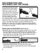
DISCONNECTING AND RECONNECTING THE PROBE: All of the probes from these 3 systems are interchangeKeyed Ends able and in the case of the 12mm dia. probe, you can add extensions to extend the camera tip up to 16 ft. (5m). To disconnect the probe Fig. 5 from the display unit, twist the retaining collar counter clockwise several turns and pull away from the unit. Then pull the probe straight away from the unit.
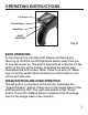
OPERATING INSTRUCTIONS LCD Screen Rotation Button Zoom Button ON/OFF BRIGHTNESS Fig. 8 BASIC OPERATION: To turn the unit on, hold the LCD display unit facing you (See Fig. 8). Roll the on/off/brightness switch away from you to turn the power on. The switch then acts as a dimmer for the LED’s in the tips of the probes. Activating the switch also illuminates the LCD screen. Note: There is no auto off. Make sure to roll the switch back towards you until it clicks to turn off the unit after use.
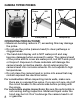
CAMERA TIPPED PROBES LED Camera LED Camera LED Camera LED LED LED LED LED LED 12mm probe tip 5.5mm probe tip LED 9mm probe tip OPERATING PRECAUTIONS! • Maximum bending radius is 2"; exceeding this may damage the probe. • Do not use the probe (camera head) to clear pathways or clogged areas. • The hand-held display unit is NOT waterproof and may become damaged when exposed to water. The camera head of the probe and its cover are waterproof, but NOT acid-proof or fireproof.
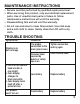
MAINTENANCE INSTRUCTIONS • Service must be performed by qualified repair personnel. • When servicing this product, only use identical replacement parts. Use of unauthorized parts or failure to follow maintenance instructions will void the warranty. • Disassembling this unit will void the warranty. • Do not use acetones to clean this product. Use mild soap and a soft cloth to clean. Gently clean the LCD with a dry cloth.
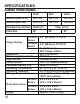
SPECIFICATIONS CAMERA TIPPED PROBES 12mm 9mm 5.5mm Resolution (pixels NTSC) 320 x 240 320 x 240 320 x 240 Resolution (pixels PAL) 704 x 576 704 x 576 704 x 576 Minimmum Focus Distance 100mm (4") Field of View 60º Image Display 10 60º 2.4" (60.9mm) TFT/LCD DCS300 Series 3.5" (88.
WARRANTY INFORMATION THREE YEAR LIMITED WARRANTY The General Tools & Instruments (General®) DCS200 Series and DCS300 Series digital video Inspection Systems are warranted to the original purchaser to be free from defects in material and workmanship for a period of three (3) years. Subject to certain restrictions, General will repair or replace this instrument, if after examination, it is determined by General to be defective in material or workmanship.
GENERAL TOOLS & INSTRUMENTS 80 White Street New York, NY 10013-3567 PHONE (212) 431-6100 FAX (212) 431-6499 TOLL FREE (800) 697-8665 e-mail: sales@generaltools.com www.generaltools.com DCS200/DCS300 Series User’s Manual Specifications subject to change without notice ©2010 GENERAL TOOLS & INSTRUMENTS NOTICE - WE ARE NOT RESPONSIBLE FOR TYPOGRAPHICAL ERRORS.