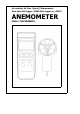
Air velocity, Air flow, Type K/J thermometer Real time data logger, 16000 Data logger no.
TABLE OF CONTENTS 1. FEATURES................................................................ 1 2. SPECIFICATIONS...................................................... 2 3. FRONT PANEL DESCRIPTION.....................................6 4. GENERAL MEASURING PROCEDURE........................... 8 4-1 Air velocity/Air temperature measurement.............8 4-2 Air flow ( CMM, CFM ) measurement..................... 9 4-3 Thermocouple ( Type K/J ) Thermometer measurement............................................
1. FEATURES * * * * * * * * * * * * * * * * * * * * * * Air velocity : m/S, Ft/min, Km/h, Knots, Mile/h, Air flow : CMM ( m^3/min. ) and CFM ( ft^3/min. ). Air temperature ( ℃, ℉ ) Type K/ Type J thermocouple thermometer. Real time data logger, build in clock ( hour-min.-sec., year-month-date ). Auto or manual data record, 16,000 Data logger no. Wide sampling time adjustment range from two seconds to 8 hours 59 minutes 59 seconds. RS232 computer interface. Can default auto power off or manual power off.
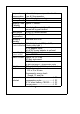
2. SPECIFICATIONS 2-1 General Specifications Circuit Display Measurement Unit Custom one-chip of microprocessor LSI circuit. LCD size : 58 mm x 34 mm. Air velocity: m/S (meters per second) Km/h ( kilometers per hour ) Ft/min ( feet per minute ) Knots ( nautical miles per hour ) Mile/h ( miles per hour ) Air flow: CMM ( m^3/min., cube meter per min. ) CFM ( m^3/min., cube feet per min. ) Air temperature: ℃, ℉ Type K/ Type J thermometer.
Temperature Compensation Data Hold Memory Recall Sampling Time of display Power off Data Output Operating Temperature Operating Humidity Power Supply Automatic temp. compensation for the Type K/J thermometer. Freeze the display reading. Maximum & Minimum value. Approx. 1 second. Auto shut off saves battery life or manual off by push button. RS 232 PC serial interface. 0 to 50 ℃. Less than 80% R.H. DC 1,5 V battery ( UM3 ) x 4 PCs, * main instrument ( Heavy duty type ). DC 9V adapter input.
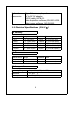
Optional Accessories Type K thermocouple probe. AC to DC 9V adapter. RS232 cable, UPCB-02. Data Acquisition software,SW-U801-WIN. Data Logger software, SW-DL2005. 2-2 Electrical Specifications (23± 5 ℃) Air velocity Measurement m/S Km/h Mile/h Knots Ft/min Range Resolution Accuracy 0.4 - 30.0 m/S 0.1 m/S ± ( 2%+0.2 m/S) 1.4 - 108.0 Km/h 0.1 Km/h ± ( 2%+0.8 Km/h) 0.9 - 67.0 Mile/h 0.1 Mile/h ± ( 2%+0.4 Mile/h) 0.8 - 58.3 Knots 0.1 Knots ± ( 2%+0.
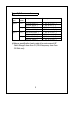
Type K/J thermometer Sensor Type Type K Type J Reso- Range lution 0.1 ℃ -50.0 to 1300.0 ℃ -50.1 to -100.0 ℃ 0.1 ℉ -58.0 to 2372.0 ℉ -58.1 to -148.0 ℉ 0.1 ℃ -100.0 to 1100.0 ℃ -50.1 to -100.0 ℃ 0.1 ℉ -58.0 to 2012.0 ℉ -58.1 to -148.0 ℉ Accuracy ± ± ± ± ± ± ± ± ( ( ( ( ( ( ( ( 0.2 0.2 0.2 0.2 0.2 0.2 0.2 0.2 % % % % % % % % + + + + + + + + 0.5 ℃ 1℃) 1℉) 1.8 ℉ 0.5 ℃ 1℃) 1℉) 1.
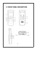
3.
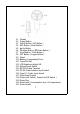
3-1 3-2 3-3 3-4 3-5 3-6 3-7 3-8 3-9 3-10 3-11 3-12 3-13 3-14 3-15 3-16 3-17 3-18 3-19 3-20 3-21 Display Power Button HOLD Button ( ESC Button ) REC Button ( Enter Button ) ▲ Up Button Function Button ( ▼ Down Button ) Send Button ( Clock Button ) SET Button ( Logger Button ) Stand Battery Compartment/Cover Tripod Fix Nut LCD Brightness Adjust VR System Reset Switch RS-232 Output Terminal DC 9V Power Adapter Input Socket Type K/J Probe Input Socket Probe Input Socket Probe Lock Switch ( System On/Off Switch
4. GENERAL MEASURING PROCEDURE The meter default value are following : * The air velocity unit is m/S. * The temperature unit is ℃. * The air flow unit is CMM. * The air flow area is meter^2 ( meter square ). * The sampling time of data logger function is 2 seconds. 4-1 Air velocity /Air Temp. measurement 1) Install the " Probe Plug " ( 3-19, Fig. 1 ) into the " Probe Input Socket " ( 3-17, Fig. 1 ). Attention : After install the " Probe Plug ", should slide Probe Lock Switch " ( 3-18, Fig.
4) Hold the " Vane Probe Handle " ( 3-21, fig. 1 ) by hand & let the " Vane Probe Head " ( 3-20, Fig. 1 ) face against the measuring air flow source, then the Display ( 3-1, Fig. 1 ) will show air velocity directly. At the same time, the display will show the air temperature value. @ The Temp. unit adjustment, please refer Chapter 5-6. Measuring Consideration : The yellow dot mark on the sensor head indicates the direction that " need to face against the air flow.
4)The display's bottom left side will show area size in Meter^2 ( or Ft^2 ) when make the air flow measurement. @ Meter^2 : Meter square, Ft^2 : Feet square. @ The adjusting procedures of area size, please refer Chapter 5-9. 5) Hold the " Vane Probe Handle " ( 3-21, fig. 1 ) by hand & let the " Vane Probe Head " ( 3-20, Fig. 1 ) is opposite to the measuring air flow source, then the Display ( 3-1, Fig. 1 ) will show air flow value.
3)Power on the meter by pressing the " Power Button " ( 3-2, Fig. 1 ). 4) For the Type K Probe, press the " Function Button " ( 3-6, Fig. 1 ) to let the bottom right LCD show the " K type " indicator For the Type J Probe, press the " Function Button " ( 3-6, Fig. 1 ) to let the bottom right LCD show the " J type " indicator 4-4 Data Hold During the measurement, press the " Hold Button " ( 3-3, Fig. 1 ) once will hold the measured value & the LCD will display a " HOLD " symbol.
b)Press the " REC Button " ( 3-4, Fig. 1 ) again, the " REC. MIN. " symbol along with the minimum value will appear on the display. If intend to delete the minimum value, just press the " Hold Button " ( 3-3, Fig. 1 ) once, then the display will show the " REC. " symbol only & execute the memory function continuously. c) To exit the memory record function, just press the " REC " button for 2 seconds at least. The display will revert to the current reading.
d)Manual Data Logger ( Sampling time set to 0 second ) Press the " Logger Button " ( 3-8, Fig. 1 ) once will save the data one time into the memory, at the same time the bottom right display will show the indicator " Recording.... " a while. Now the Data logger function is executed. The upper display will show " DATA " indicator along with " REC " marker. e) Memory full Under execute the data logger, if the bottom right display show the " Full ", it indicate the memory data already over 16,000 no.
5. ADVANCED ADJUSTMENT PROCEDURES When execute the following Advanced Adjustment Procedures should cancel the " Hold function " and the " Record function " first. The display will not show the " HOLD " and the " REC " marker. a. Press the " SET Button " ( 3-8, Fig. 1 ) at least two seconds until the lower display show XXXXX Memory Space * If push the " ESC Button " ( 3-3, Fig. 1 ) will escape the selecting function and return to the normal measuring display. b.
c. When make Advanced Adjustment Procedure will use the following key buttons : ESC Button ( 3-3, Fig. 1 ), Enter Button ( 3-4, Fig. 1 ) ▲ Up Button ( 3-5, Fig. 1 ), ▼ Down Button ( 3-6, Fig. 1 ) SET Button ( 3-8, Fig. 1 ), SEND Button ( 3-7, Fig. 1 ) 5-1 Check Memory Space To check the balance data numbers that exist into the memory ( allow memorize data no. ). XXXXX Memory Space @ XXXXX is the balance data numbers, for example XXXXX=15417.
5-4 Sample Time Setting * Use ▲ Up Button, ▼ Down Button and Enter ( →) Button to select the expect Sample Time ( HOUR-MIN.-SEC.). * After finish the Sample Time adjustment, Push the " Enter Button " , then press the " ESC Button " will quite and save the clock data into the memory. 5-5 Auto Power Off Default Setting * Use ▲ Up Button, ▼ Down Button to select " 1 " or " 0 ". 1 = Auto power On. 0 = Auto power Off.
5-7 Air Velocity Unit Default Setting * Use ▲ Up Button, ▼ Down Button to select the default Air Velocity unit as : m/S, Ft/min, Km/h, Knots, Mile/h, * After finish the Air Velocity unit adjustment, push the " Enter Button " , then press the " ESC Button " will quite and return to the normal measurement display. 5-8 Air Flow Unit Default Setting * Use ▲ Up Button, ▼ Down Button to select the default Air Flow unit as : CMM or CFM CMM : cube meter per minute. CFM : cube feet per minute.
5-10 Escape from the SETTING function Press the " ESC Button " once a while will quite and return to the normal measurement display. 6. HOW TO SEND THE DATA OUT FROM THE METER 1)If intend to send the data out from the meter, it should cancel the " Hold function " and the " Record function " first. The display will not show the " HOLD " and the " REC " marker. 2)Press the " SEND Button " ( 3-7, Fig. 1 ) at least 2 seconds until the bottom right display show " Transmit mode ", then release the button.
The meter can save 16,000 data max. , those data will saved into 250 memory block max. * One " Memory Block " means : The data that save into one routine Data Logger procedures ( Push " REC " button , following push the " Logger " button to save the data, the display will show the " REC " and " DATA " . After save the data push the " Logger " button, following push the " REC " button, will exist the Data Logger function. The " REC " and " DATA " indicator of LCD will be disappeared ).
3) Until the desired Memory Block no. be selected. Push the " Send Button " ( 3-7, Fig. 1 ) once, the data in the Memory Block will send out. During the data send out, the bottom right display will show the " Sending Data ! " indicator. When data already send out completely, the bottom right display will show the Transmit mode " indicator again. 5) Push the " ESC Button " ( 3-3, Fig. 1 ) will exist the data sending function and return to the normal display.
7. RS232 PC SERIAL INTERFACE The instrument has RS232 PC serial interface via a 3.5 mm terminal ( 3-14, Fig. 1 ). The data output is a 16 digit stream which can be utilized for user's specific application. A RS232 lead with the following connection will be required to link the instrument with the PC serial port. Meter PC (9W 'D" Connector) (3.5 mm jack plug) Center Pin........................Pin 4 Ground/shield.....................Pin 2 Pin 5 2.
Each digit indicates the following status : D0 End Word = 0D D1 & D8 Display reading, D1 = LSD, D8 = MSD For example : If the display reading is 1234, then D8 to D1 is : 00001234 D9 Decimal Point(DP), position from right to the left 0 = No DP, 1= 1 DP, 2 = 2 DP, 3 = 3 DP D10 Polarity 0 = Positive 1 = Negative D11 & Annunciator for Display D12 ℃ = 01 Knot = 09 mile/h = 12 ℉ = 02 Km/h = 10 CMM = 84 m/S = 08 ft/min = 11 CFM = 85 D13 When send the upper display data = 1 When send the lower display data = 2 D14
8. BATTERY REPLACEMENT 1) The time to change the UM3 ( 1.5 V ) x 4 PCs When the left corner of LCD display show " ", it is necessary to replace the batteries ( UM3/1.5 V x 4 PCs ). The time to change the CR2032 ( 3V silver battery ) When the clock is not accurate or power off the meter then on, the clock time is disappeared or garbled, it is necessary to replace the battery ( CR2032 ) 2)Slide the " Battery Cover " ( 3-10, Fig. 1 ) away from the instrument and remove the battery.
1)Slide the " Probe Lock Switch/System On/Off Switch " from the On to Off, then On again. 2)Or during the Power On, used a pin tool to push the " System Reset Switch " ( 3-13, Fig. 1 ) once a while. 10. OPTIONAL ACCESSORIES RS232 cable UPCB-02 Data Logger software SW-DL2005 Data Acquisition software SW-U801-WIN * Isolated RS232 cable. * Used to connect the meter to the computer * Software the used to download the data logger ( data recorder ) from the meter to computer.
Thermocouple Probe (Type K) TP-01 Thermocouple Probe (Type K), TP-02A Thermocouple Probe (Type K), TP-03 Surface Probe (Type K), TP-04 * Measure Rage: -40 ℃ to 250 ℃, -40 ℉ to 482 ℉. * Max. short-tern operating Temperature: 300 ℃ (572 ℉). * It is an ultra fast response naked-bead thermocouple suitable for many general purpose application. * Measure Range: -50 ℃ to 900 ℃, -50 ℉ to 1650 ℉. * Dimension:10cm tube, 3.2mm Dia. * Measure Range: -50 ℃ to 1200 ℃, -50 ℉ to 2200 ℉. * Dimension: 10cm tube, 8mm Dia.