CMR35 Manual FINAL4_020911:awb 2/9/11 11:54 AM Page 1 WIRELESS MULTI-NODE DATA LOGGING TRUE RMS CLAMP MULTIMETER SYSTEM USER’S MANUAL Receiver Transmitter CMR35 SERIES CMR35–910MHz CMR35A–912.4MHz Please read this manual carefully and thoroughly before using this product.
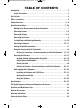
CMR35 Manual FINAL4_020911:awb 2/9/11 11:54 AM Page 2 TABLE OF CONTENTS Introduction . . . . . . . . . . . . . . . . . . . . . . . . . . . . . . . . . . . . . . . . . . . . . . . . . . . . . . . . . . . 3 Safety Precautions . . . . . . . . . . . . . . . . . . . . . . . . . . . . . . . . . . . . . . . . . . . . . . . . . . 3 Key Features . . . . . . . . . . . . . . . . . . . . . . . . . . . . . . . . . . . . . . . . . . . . . . . . . . . . . . . . . . . 4 What’s in the Case . . . . . . . . . . . . . . . . .
CMR35 Manual FINAL4_020911:awb 2/9/11 11:54 AM Page 3 INTRODUCTION Thank you for purchasing General Tools & Instruments’ CMR35 Series Wireless Data Logging Clamp Multimeter System. Please read this user’s manual carefully and thoroughly before using the instrument. There are two CMR35 systems: The CMR35 system operates at 910MHz and the CMR35A system operates at 912.4MHz.
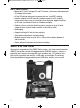
CMR35 Manual FINAL4_020911:awb 2/9/11 11:54 AM Page 4 KEY FEATURES • Measures AC and DC voltages, AC and DC currents, resistances, and frequency of AC voltages and currents • AC and DC voltage and current measurements are “true RMS” readings • Includes software and USB cable that connect receiver to a PC, enabling measurements from up to six transmitters to be displayed, logged (stored on) an SD card, and viewed in Excel on a Windows computer • Software also can calculate electricity (power) charges for up
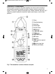
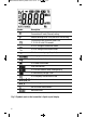
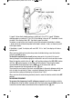
CMR35 Manual FINAL4_020911:awb 2/9/11 11:54 AM Page 5 PRODUCT OVERVIEW Before using the transmitter and receiver together, learn how to make some basic measurements using the transmitter unit alone. To begin, familiarize yourself with Figures 1 and 2. Fig. 1 shows the transmitter unit’s controls, indicators and jacks. Fig. 2 shows the symbols used by the transmitter’s liquid-crystal display, as well as their positions.
CMR35 Manual FINAL4_020911:awb 2/9/11 11:54 AM Page 6 Symbol Description Transmission ID code (Channel) setting Antenna blinking while in the process of transmitting Transmission span selection; options are 2, 10, 30, 60, and 120 seconds Lit in DC voltage measurement mode Lit in AC voltage measurement mode Lit when measuring negative polarity Autoranging on indicator Lit in continuity check mode Lit in diode check mode Data hold indicator Lit in relative mode or when zeroing display Lit when battery volta
CMR35 Manual FINAL4_020911:awb 2/9/11 11:54 AM Page 7 OPERATING INSTRUCTIONS MAKING BASIC MEASUREMENTS WITH THE TRANSMITTER As you make measurements, be aware that pressing the HOLD button on the transmitter (callout 6 of Fig. 1) temporarily stores (memorizes) the displayed reading. This feature comes in handy when making measurements under low-light conditions or in tight spaces (under counters, in crawl spaces or attics, or inside electrical panels) where the display is out of sight.
CMR35 Manual FINAL4_020911:awb 2/9/11 11:54 AM Page 8 In DC current measurement mode, the CMR35T selects a 0 to 400A measurement range unless the input is greater than 400A. In this case, the unit automatically switches to a full-scale range of 0 to 600A. Read the value after it stabilizes. If the symbol appears at the left of the measured value, as shown in Fig. 2, the current flow is opposite the direction indicated by the polarity marks on the clamp.
CMR35 Manual FINAL4_020911:awb 2/9/11 11:54 AM Page 9 • WARNING • To avoid exposing yourself to a harmful or a fatal voltage and damaging the transmitter, make sure that the potential you are attempting to measure is less than 600VAC. As in current measurement mode, the CMR35T automatically chooses the narrowest measurement range that includes the tested value. The four available full-scale ranges are 0 to 4V, 0 to 40V, 0 to 400V, and 0 to 600V. Read the measured value once it stabilizes.
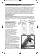
CMR35 Manual FINAL4_020911:awb 2/9/11 11:54 AM Page 10 RED PROBE BLACK PROBE A “good” silicon diode should produce a reading of 0.5 to 0.7V. A “good” GE diode should produce a reading of 0.2 to 0.3V. If the reading is close to “0”, the diode is shortcircuited. If the display reads “OL”, the diode is open-circuited.
CMR35 Manual FINAL4_020911:awb 2/9/11 11:54 AM Page 11 • WARNING • To avoid exposing yourself to a harmful or a fatal voltage and damaging the transmitter, make sure that the AC voltage or current whose frequency you are measuring has an amplitude of less than 600V. As in current measurement mode, the CMR35T automatically chooses the narrowest measurement range that includes the tested value. The six available full-scale ranges are 0 to 5Hz, 0 to 50Hz, 0 to 500Hz, 0 to 5kHz, 0 to 50kHz, and 0 to 100kHz.
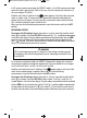
CMR35 Manual FINAL4_020911:awb 2/9/11 11:54 AM Page 12 USING THE RECEIVER WITH THE TRANSMITTER Three buttons on the front panel of the transmitter must be pressed to prepare it to wirelessly send readings to the receiver. One is the TX ON button (callout 9 of Fig. 1). Pressing this button activates transmission mode and causes the symbol to appear at the upper left of the display, as shown in the figure below. Pressing the button again ends transmission and causes the symbol to disappear.
CMR35 Manual FINAL4_020911:awb 2/9/11 11:54 AM Page 13 Transmission span setting ID code (Channel) setting Before moving on to operating the receiver, familiarize yourself with Figures 3 and 4. Fig. 3 shows the controls, indicators and jacks of the receiver. Fig. 4 shows the symbols used by the receiver’s liquid-crystal display and their positions.
CMR35 Manual FINAL4_020911:awb 2/9/11 11:54 AM Page 14 RIGHT SIDE ▲ Fig. 3. The receiver’s controls, indicators and jacks 햲 Nameplate 햳 Liquid-crystal display 햴 POWER button 햵 READ button. Main use is for recalling stored maximum and minimum measurements. Secondary function (indicated by ▲ stencil at right of button) is for adjusting settings of clock and alarm 햶 HOLD MAX-H button. Locks maximum measured value 햷 MAX. MIN. button. Main use is for entering maximum/minimum measurement mode.
CMR35 Manual FINAL4_020911:awb 2/9/11 11:54 AM Page 15 Symbol Description Transmission ID code (Channel) setting (1 to 6) When blinking, indicates signal being received from transmitter Indicates displayed value is memorized maximum or minimum measurement Indicates displayed value is recalled maximum or minimum measurement Lit in alarm mode when measured value is higher or lower than alarm setpoint Lit in 24-hour clock mode Lit in DC voltage measurement mode Lit in AC voltage measurement mode Lit when mea
CMR35 Manual FINAL4_020911:awb 2/9/11 11:54 AM Page 16 OPERATING THE RECEIVER To power on, press the button. To power off, press the at least three seconds. READING, HOLDING, STORING AND RECALLING DATA button and hold it for To use the button to recall stored maximum or minimum values, follow the instructions embedded in the next two figures. To call up a display without stored MAX/MIN data: .
CMR35 Manual FINAL4_020911:awb 2/9/11 11:54 AM Page 17 To use the button to hold the current reading: To enter MAX-HOLD mode and recall MAX measurements: To use the button to store maximum and minimum values, follow the instructions embedded in the next figure.
CMR35 Manual FINAL4_020911:awb 2/9/11 11:54 AM Page 18 To use the secondary function of the button to move the position of the blinking digit when setting the clock and alarm, refer to the figure below. When the digit is blinking, press the key to move to the next digit. SETTING ALARMS AND SETPOINTS To use the figures.
CMR35 Manual FINAL4_020911:awb 2/9/11 11:54 AM Page 19 To set an alarm setpoint Press ALARM button to enter alarm function mode Press SEARCH button Enter setpoint setting mode.
CMR35 Manual FINAL4_020911:awb 2/9/11 11:54 AM Page 20 SETTING THE CLOCK Press the button to enter clock setting mode. You must then press the ▲ or ► button within two seconds or the first screen below will disappear. To set the clock Press button, and then press ▲ or ► button immediately to cause left digit to blink Use ▲ or ► button to set clock Press button or wait 10 seconds to complete clock setting.
CMR35 Manual FINAL4_020911:awb 2/9/11 11:54 AM Page 21 ID code (Channel) setting Press SEARCH button and hold for two seconds to enter ID code selection mode Press CLOCK SET button to switch selected ID Code (Channel) on or off ID code (Channel) from 1 to 6 Press CHANNEL button to switch to different ID code (Channel) Press HOLD/MAX-H button to switch selected ID code (Channel) on or off Press SEARCH button and hold for two seconds to save setting and return receiver unit to measuring mode 21
CMR35 Manual FINAL4_020911:awb 2/9/11 11:54 AM Page 22 DATA LOGGING WITH A COMPUTER The CMR35 system includes the software and cable needed to transfer measurements made by the transmitter and relayed through the receiver to any computer running a Windows7, Windows Vista or WindowsXP operating system.
CMR35 Manual FINAL4_020911:awb 2/9/11 11:54 AM Page 23 10. The CMR35 Flash Player 9 screen will reappear on your desktop. Left-click the “USB Installation” button. 11. The next screen will be a File Download-Security Warning. Respond to the question “Do you want to run or save this file?” (the 20.0KB InstallUSB.exe file) by clicking Run. 12. The next screen will be a Windows User Account Control dialog box.
CMR35 Manual FINAL4_020911:awb 2/9/11 11:54 AM Page 24 USING THE SOFTWARE To use the software, refer to the callouts accompanying the following partial screen shots. Each screen shot and set of callouts detail the functions available from one of the pull-down buttons on the software’s main menu bar. The explanations in the View menu section cover the features of the software’s three main windows: the Monitor, the Table and the Graph. The File menu 햲 Open (.
CMR35 Manual FINAL4_020911:awb 2/9/11 11:54 AM Page 25 The Edit menu The View menu The four options above also are available from the toolbar below the main menu, as shown below 햲 The Table window 25
CMR35 Manual FINAL4_020911:awb 2/9/11 11:54 AM Page 26 햳 The Monitor window 햴 The Graph window 햵 The Electric Power Cost Monitor window Display of this window can be enabled using the View menu or the toolbar below the main menu. However, the Electric Power Cost Monitor window will display only if the three parameters in the bottom row—V, P.F. (Power Factor) and Unit Price—have been entered using the Setup menu. If you do not know the P.F.
CMR35 Manual FINAL4_020911:awb 2/9/11 11:54 AM Page 27 If you know the line voltage of your system, enter it in the “V” window at left (110V is shown). If you are not sure of the line voltage, measure it by inserting the transmitter’s black and red probes in a power outlet. Read the value and enter it in the “V” window at left. To use the Electric Power Cost Monitor window, the CMR35 system’s transmitter(s) must be operating in DCA (DC Amperes) or ACA (AC Amperes) measurement mode.
CMR35 Manual FINAL4_020911:awb 2/9/11 11:54 AM Page 28 The Option menu Table tab Select table background color and type of grid line (flat, inset or raised) 28
CMR35 Manual FINAL4_020911:awb 2/9/11 11:54 AM Page 29 The Window menu Returns Monitor, Table, Graph and Electric Power Cost Monitor windows to default positions The Help menu Open Wireless Clamp Meter User’s Manual. * Windows, Windows 7, Windows Vista and Windows XP are registered trademarks of Microsoft Corporation.
CMR35 Manual FINAL4_020911:awb 2/9/11 11:54 AM Page 30 SPECIFICATIONS ELECTRICAL SPECIFICATIONS AC Current Measurement Range Resolution Accuracy Maximum input current 400A 0.1A ±(1.8% of reading + 10 digits) 600A 1A ±(1% of reading + 5 digits) 600A 600A DC Current Measurement Range Resolution Accuracy Maximum input current 400A 0.1A ±(1.8% of reading + 10 digits) 600A 1A ±(1% of reading + 5 digits) 600A 600A DC Voltage Measurement Range Resolution Accuracy 400mV 0.1mV +(0.
CMR35 Manual FINAL4_020911:awb 2/9/11 11:54 AM Page 31 Resistance Measurement Range Resolution Accuracy 400Ω 0.1Ω 4kΩ 0.001kΩ 40kΩ 0.01kΩ 400kΩ 0.1kΩ 4MΩ 0.001MΩ ±(3% of reading + 5 digits) 40MΩ 0.01MΩ ±(5% of reading + 5 digits) ±(1% of reading + 5 digits) Maximum input voltage Remarks --Open circuit voltage is ~0.4V --Measuring current varies with resistance measured 600V Continuity Check Range Resolution Accuracy Maximum input voltage 400Ω 0.
CMR35 Manual FINAL4_020911:awb 2/9/11 11:54 AM Page 32 GENERAL SPECIFICATIONS Distance between transmitter and receiver Transmission frequency 333 ft. (100m) maximum; less with obstacles in path and when either unit is inside metallic structure 910MHz (CMR35) or 912.
CMR35 Manual FINAL4_020911:awb 2/9/11 11:54 AM Page 33 FCC RADIO FREQUENCY INTERFERENCE COMPLIANCE DISCLOSURE This device complies with Part 15 of U.S. Federal Communications Commission (FCC) rules governing radio frequency devices. Operation is subject to the following two conditions: (1) this device may not cause harmful interference, and (2) this device must accept any interference received, including interference that may cause undesired operation.
CMR35 Manual FINAL4_020911:awb 2/9/11 11:54 AM Page 34 OPERATION & MAINTENANCE TIPS To ensure the accuracy of measurements, avoid using the transmitter and receiver units: • In electrically noisy environments • Near conductors carrying strong currents • In rain or snow • In extreme heat (including in direct sunlight) or cold • Without fully charged batteries Whenever measurements appear erratic or the symbols , or appear on the display, replace the batteries of both units immediately.
CMR35 Manual FINAL4_020911:awb 2/9/11 11:54 AM Page 35 RETURN FOR REPAIR POLICY Every effort has been made to provide you with a reliable product of superior quality.
CMR35 Manual FINAL4_020911:awb 2/9/11 11:54 AM Page 36 GENERAL TOOLS & INSTRUMENTS 80 White Street New York, NY 10013-3567 PHONE (212) 431-6100 FAX (212) 431-6499 TOLL FREE (800) 697-8665 e-mail: sales@generaltools.com www.generaltools.com CMR35 Series User’s Manual Specifications subject to change without notice ©2011 GENERAL TOOLS & INSTRUMENTS NOTICE - WE ARE NOT RESPONSIBLE FOR TYPOGRAPHICAL ERRORS.