DATA LOGGING HOT WIRE ANEMOMETER with CFM/CMM and 8:1 IR THERMOMETER USER’S MANUAL CIH20DL Please read this manual carefully and thoroughly before using this product.
TABLE OF CONTENTS Introduction . . . . . . . . . . . . . . . . . . . . . . . . . . . . . . . . . . . . . . . . . . . . . . . . 3 – 4 Key Features . . . . . . . . . . . . . . . . . . . . . . . . . . . . . . . . . . . . . . . . . . . . . . . . . . 4 Safety Instructions . . . . . . . . . . . . . . . . . . . . . . . . . . . . . . . . . . . . . . . . . . . . . 5 What’s in the Case . . . . . . . . . . . . . . . . . . . . . . . . . . . . . . . . . . . . . . . . . . . . . 5 Product Overview . . . . . . . . . . . .
INTRODUCTION Thank you for purchasing General Tools & Instruments’ CIH20DL Data Logging Hot Wire Anemometer with CFM/CMM and 8:1 IR Thermometer. Please read this user’s manual carefully and thoroughly before using the instrument.
The CIH20DL can be configured to display air speed in any of five Imperial or metric units, airflow volume in CFM or CMM, and temperature in degrees Fahrenheit or Celsius. The instrument’s IR thermometer, which can be precisely aimed by a low-power laser pointer, assumes by default that its target has an emissivity of 0.95, which is true for 90% of applications. The meter is normally powered by one “9V” battery (included).
SAFETY INSTRUCTIONS CAUTION! The CIH20DL’s targeting laser is a Class II type that emits less than 1mW of power between 630nm and 660nm. Avoid direct eye contact with laser light radiation. U.S. law prohibits pointing a laser beam at aircraft; doing so is punishable by a fine of up to $10,000 and imprisonment. WHAT’S IN THE CASE The CIH20DL and its accessories come in a custom molded plastic case.
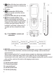
4. button: Activates laser pointer when enabled (unless readouts are displaying recalled values) 5. � button 6. (Anemometer HOLD) button: Freezes air speed and airflow volume readings only 7. AC power/USB cable jack (on left side) 8. A two-function button: Laser pointer enable/disable and backlight on/off. Pressing button four times cycles through the four possible combinations of states (see figure below). After the backlight is activated, it stays on for 15 seconds and then automatically shuts off.
Fig. 2.
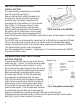
SETUP INSTRUCTIONS INSTALL BATTERY The meter’s battery compartment is accessible from the back of the unit (Fig. 3). Before installing the 9V battery included in the carrying case, remove the plastic covering its terminals. Open the battery compartment by pushing the tab at the bottom of its cover forward (Fig. 3, Step 1). Lift the cover and set it aside (Step 2). Then plug the battery into the wired socket inside the compartment. The terminals of Fig. 3.
To power on the meter, press the button. The display will initially show the clock icon at upper left and numbers on the primary readout counting down from 15. The numbers track the time needed to heat the hot wire to prepare it for use. After 15 seconds, the meter will be ready for use. It will automatically enter “normal” (air speed or airflow volume + temperature) measurement mode and display a screen similar to Fig. 5.
MEASURING SURFACE TEMPERATURE To use the meter’s IR thermometer to measure the surface temperature of an object from a distance, make sure the meter is in “normal” measurement mode, with the primary (middle) readout tracking air speed or airflow volume and the tertiary (lower) readout tracking air temperature. Then make sure the laser pointer is enabled (indicated by the icon at the top of the display). It may be necessary to press the button once or R Temptwice to enable the pointer.
Fig. 7 is a flowchart of the menu made available by briefly pressing the MODE SET button. Starting from normal measurement mode, one press of the button makes all three readouts show the maximum values of the three main parameters measured since the meter was powered up. The term MAX appears at the lower left of the display to indicate what the readings represent.
To retrieve other triple sets of measurements in either order (newest to oldest, or oldest to newest), use the � and � buttons, respectively. For example, if the first set of values retrieved (the most recently stored) is tagged DATA2, pressing the � button would retrieve the values stored in memory location DATA1. These represent the next oldest measurements, compared to DATA2. To continue retrieving data using a reverse timeline (newest to oldest), continue to press the � button.
Fig. 8. The Advanced Settings Menu Normal Measuring mode Press and hold the MODE SET button for 3+ seconds to enter/exit menu from/to normal measuring mode. Air Speed or Airflow Volume mode Press the � or � button to select CMM, CFM (for Airflow Volume mode) or m/s, ft/min, km/h, mile/h, knots (for Air Speed mode). When your choice flashes, press the MODE SET button to store it.
DATA LOGGING WITH A COMPUTER In addition to making and displaying real-time air speed, airflow volume and temperature measurements and storing up to nine sets of these readings in nonvolatile memory, the CIH20DL also can make and time-stamp up to 20,000 measurements over extended periods of time at user-selected sampling rates. These measurements, called data logs, are stored in a separate internal memory.
10. You may or may not be prompted now to restart your computer to complete installation of the Anemometer Application. If you are prompted to do so, click Restart. Whether or not you restart, note that an Anemometer Application icon has been added to your desktop, start button, or both locations. To facilitate access to the program, right-click on whichever icon has been added and pin it to both locations and your taskbar.
Fig. 11. the Anemometer Application's dashboard To access the dashboard, you must use this pulldown to select the number of the COM port you are using to connect the meter. This is the number you were advised to write down earlier. If you have forgotten it, you can still identify the “correct” port by trial and error. Selecting the correct COM port will illuminate the green STATUS light on the small overlaid screen and make the CONNECT virtual button available to press.
On the dashboard, the default units are °F for temperature and m/s for air speed. To change the air speed unit, left-click the red box containing m/s and select one of the four other units as the default. To switch to °F as the IR and air temperature unit, click on °F in the red box. These defaults must be reset each time you the open the program. Using the Meter to Log Data Before logging data, close the Anemometer AP program and disconnect the CIH20DL from your computer in that order (see Warning on p.
Be aware that after you reconfigure the power cable as a USB cable and before you connect the meter to your computer, the meter will automatically resume drawing power from its internal battery. The switch will re-enable the Auto Power Off function, which will then automatically power the meter off if no buttons on it are pushed within any 10-minute interval.
Viewing Record Data Graphically You can also view Record data by using the dashboard’s integrated chart function. With the meter connected to your computer (indicated by a green light at the upper left of the dashboard and the word LINK on the bottom line of the meter’s LCD, click on the OPEN virtual button under CHART at the bottom of the dashboard. A screen similar to Fig. 12 will appear on your computer’s display.
Other selections in the pulldown menus that appear when you right-click on any of the three icons of the graph palette can be used to: • Make other chart items visible • Auto-scale plots along their X and Y axes • Export images • Copy data • Change the way that plots are updated • Add descriptions and tips to charts It is also possible to left-click on two of the three icons of the graph palette.
Note the tabular format of the data as well as the column headings and the time stamps (the third column in Notepad and WordPad, and Column C in Excel). Like Record data, Data Logs comprise three sets of readings (IR Temperature, Air Velocity and Air Temperature) that are expressed in default units and displayed in chronological order. Unlike Record data, the time stamps of Data Logs begin when you started data logging and stop when you stopped logging.
SPECIFICATIONS Air Speed Measurement Range Air Speed Measurement Basic Accuracy Air Speed Measurement Resolution Airflow Volume Measurement Range Airflow Volume Measurement Basic Accuracy Airflow Volume Measurement Resolution Air Temperature Measurement Range Air Temperature Measurement Basic Accuracy Air Temperature Measurement Resolution IR (Surface) Temperature Measurement Range IR Temperature Measurement Accuracy IR Temperature Measurement Resolution IR Thermometer Emissivity IR Thermometer Distance-to-
MAINTENANCE TIPS Remove the battery before storing the meter for an extended period of time. Do not drop or disassemble the meter or immerse it in water. WARRANTY INFORMATION General Tools & Instruments’ (General’s) CIH20DL Data Logging Hot Wire Anemometer with CFM/CMM and 8:1 IR Thermometer is warranted to the original purchaser to be free from defects in material and workmanship for a period of one year.
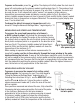
APPENDIX mm 25@200 inches 1@8 50@400 2@16 75@600 3@24 Numbers indicate spot size@distance The field of view of the CIH20DL's IR thermometer HOW TO MAKE ACCURATE IR MEASUREMENTS The CIH20DL has a distance-to-spot (D:S) ratio of 8:1. This means that the target area (spot) whose infrared radiation (temperature) is being measured increases in diameter by 1 inch for every 8 inches you move away from the target.
To eliminate measurement error, the CIH20DL must be moved close enough so the motor is the only object in the target area of its IRT (see below figure). For a motor with an area of 1 ft2 and using an IRT with a D:S ratio of 8:1, the optimum measurement distance would be 8 ft.
NOTES __________________________________________________________________________ __________________________________________________________________________ __________________________________________________________________________ __________________________________________________________________________ __________________________________________________________________________ __________________________________________________________________________ ________________________________________________________
NOTES __________________________________________________________________________ __________________________________________________________________________ __________________________________________________________________________ __________________________________________________________________________ __________________________________________________________________________ __________________________________________________________________________ ________________________________________________________
GENERAL TOOLS & INSTRUMENTS 80 White Street New York, NY 10013-3567 PHONE (212) 431-6100 FAX (212) 431-6499 TOLL FREE (800) 697-8665 e-mail: sales@generaltools.com www.generaltools.com CIH20DL User’s Manual Specifications subject to change without notice ©2011 GENERAL TOOLS & INSTRUMENTS NOTICE - WE ARE NOT RESPONSIBLE FOR TYPOGRAPHICAL ERRORS.