Pro-Doweling Kit USER’S MANUAL #840 Please read this manual carefully and thoroughly before using this product.
General Tools & Instruments would like to thank you for your purchase. For more information on our complete line of products, visit www.GeneraITools.com TABLE OF CONTENTS Package Contents . . . . . . . . . . . . . . . . . . . . . . . . . . . . . . . . . . . 3 Safety Instructions . . . . . . . . . . . . . . . . . . . . . . . . . . . . . . . . . . 3 Before You Get Started . . . . . . . . . . . . . . . . . . . . . . . . . . . . . . . 3 Selecting Dowel Size . . . . . . . . . . . . . . . . . . . . . . . . . . .
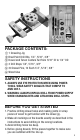
PACKAGE CONTENTS: 1 Doweling Jig Brad Point Drill Bits, 1/4", 5/16", 3/8" Dowel and Tenon Centers Set from 3/16" ID to 1/2" OD 3 Drill Stops 1/4", 5/16", 3/8" 30 Dowel Pins, 10 Each 1/4", 5/16", 3/8" Wood Glue SAFETY INSTRUCTIONS 1. ALWAYS USE EYE PROTECTION WHEN USING POWER TOOLS. WEAR SAFETY GOGGLES THAT COMPLY TO ANSI 287.1. 2. WARNING: ALWAYS UNPLUG DRILL FROM POWER SUPPLY WHEN CHANGING BITS AND ATTACHING DRILL STOPS. BEFORE YOU GET STARTED 1.
SELECTING DOWEL SIZE The dowel size is limited by the thickness of the work piece. Use Table 1 to help you choose the proper dowel size for your project. Board Thickness 1/2" – 9/16" 5/8" – 11/16" 11/16" – 15/16" 1" or greater Dowel Size 3/16" or 1/4" 5/16" 3/8" 7/16" or 1/2" Table 1 G C A D H B F E A. SCORE LINE B. CLAMP SCREW C. FIXED JAW D. INDEX MARK 4 E. SLIDE LOCK SCREW F. SLIDE G. SCALE ROD H.
INSTRUCTIONS FOR EDGE-TO-EDGE JOINTS 1. Place boards that you want to join in the final position and mark them “A” and “B” (See Figure 1). 2. Now position the boards so the surfaces to be joined face you. Using a square, align the edges of the boards (See Figure 2). NOTE: To fit in the jig, the combined width of both boards must not exceed 4 inches. When the combined width exceeds 4 inches, only one board can be in the jig at a time (See Figure 2). 3. Once aligned, use a clamp to secure the boards. 4.
EXAMPLE: If both of the boards to be joined are each one inch thick, move the SLIDE (F) so the arrow aligns with the 1/2" graduation on the SCALE ROD (G) to drill the first hole. Then move the SLIDE (F) so the arrow aligns with the 1-1/2" graduation on the SCALE ROD (G) to drill the second hole. 9. Lift TURRET (H) and turn until the correct size hole is aligned with the INDEX MARK (D). The TURRET (H) will snap into place when properly located. 10. ENSURE THE DRILL IS TURNED OFF.
INSTRUCTION FOR USE OF DOWEL CENTERS These dowel centers help to make it easy to precisely align the holes of two pieces of stock to be joined by a doweled joint— for example, a shelf and each of its supports. They can be used in conjunction with a dowel jig to show where the joining holes need to be drilled. Drill one set of holes with a diameter of 1/4'', 5/16'', 3/8'' or 1/2'' in one piece of stock (see photo).
INSTRUCTIONS FOR T-BUTT JOINTS NOTE: When using this jig to make T-Butt joints, the width of either surface to be drilled cannot exceed 4 inches. 1. Place boards you want to join in the final position and mark them “A” and “B”. Use a square to align the two boards and mark a line along the edge of board “A” on the short side of board “B” (See Figure 8). Figure 8 2. Flip board “A” flat so it lies on board “B”. Use a square to ensure the edges are still aligned (See Figure 9). Clamp the boards together. 3.
. Loosen SLIDE LOCK SCREW (E) and, starting from the marked line on board “B”, move the SLIDE (F) along the SCALE ROD (G) until the distance the SLIDE (F) is away from the line is half the thickness of board “A”. Use Figure 11 the graduations marked on the SCALE ROD (G) for measuring (See Figure 11). Once aligned, tighten SLIDE LOCK SCREW (E). 10. Lift TURRET (H) and turn until the correct size hole is aligned with the INDEX MARK (D). The TURRET (H) will snap into place when properly located. 11.
INSTRUCTIONS FOR CORNER JOINTS NOTE: When using this jig to make corner joints, the width of either surface to be drilled cannot exceed 4 inches. 1. Place boards you want to join in the final position and mark them “A” and “B”. Use a square to Figure 14 ensure proper alignment (See Figure 14). 2. Flip board “A” flat so it lies on board “B”. Use a square to ensure the edges are still aligned (See Figure 15). Clamp the boards together. 3.
9. Loosen SLIDE LOCK SCREW (E) and move the SLIDE (F) along the SCALE ROD (G) until the distance the SLIDE (F) is away from the edge is half the thickness of board “A”, Use the graduations marked on the SCALE ROD (G) for measuring (See Figure 18), Figure 18 Once aligned, tighten SLIDE LOCK SCREW (E). 10. Lift TURRET (H) and turn until the correct size hole is aligned with the INDEX MARK (D), The TURRET (H) will snap into place when properly located. 11. ENSURE THE DRILL IS TURNED OFF.
Juego de Amortajadora Profesional GUIA DEL USUARIO #840 Por favor lea cuidadosamente esta guía del usuario antes de utilizar éste producto.
GRACIAS: General Tools & Instruments desea agradecerle por su compra. Para más información sobre nuestra línea completa de productos, visite: www.GeneralTools.com CONTENIDO DEL PAQUETE 1 Amortajadora Brocas para Madera de 1/4", 5/16" y 3/8" Juego de guías para centros de orificios y espigas de 3/16" de Diám. Int. a 1/2" de Diám. Ext. 3 topes para brocas de 1/4", 5/16" y 3/8" 30 espigas: 10 de 1/4", 10 de 5/16" y 10 de 3/8" Cola para madera INSTRUCCIONES DE SEGURIDAD 1.
ANTES DE COMENZAR 1. Practique taladrar orificios de mortaja y hacer juntas con espigas en retazos de madera para familiarizarse con la amortajadora. 2. Para evitar taladrar en lugares equivocados, haga todas las marcas en los tableros exactamente como se describe en las instrucciones. 3. Evite taladrar orificios demasiado profundos. 4. Antes de encolar las espigas, encaje las piezas para asegurarse de estar satisfecho con el alineamiento.
INSTRUCCIONES PARA JUNTAS DE CANTO CON CANTO 1. Coloque las tablas que desea unir en su posición final y márquelas “A” y “B”. (Vea la Figura 1). 2. Ahora posicione las tablas con las superficies a unirse hacia usted. Alinee los bordes de las tablas con una escuadra (Vea la Figura 2). NOTA: Para insertar las dos tablas a la vez en la amortajadora, el espesor combinado no debe exceder 10cm (4"); de lo contrario sólo se podrá amortajar una tabla a la vez. (Vea la Figura 2). 3.
graduaciones en LA VARILLA DE ESCALA (G) para centrar el DESLIZADOR (F) (Vea la Figura 5). Una vez alineado, ajuste el TORNILLO de seguro de deslizamiento lateral (E). EJEMPLO: Si cada una de las tablas a unirse tiene una pulgada de espesor, para taladrar el primer orificio, mueva el DESLIZADOR (F) alineando la flecha con la marca de 1/2" en la Varilla de Escala (G). Luego, para taladrar el segundo orificio mueva el Deslizador (F) alineando la flecha con la marca de 1-1/2" en la Varilla de Escala (G). 9.
16. Aplique cola a las espigas e insértelas en los orificios de mortaja en la tabla “A”. Alinee los orificios en la tabla “B” con las espigas en la tabla “A” y junte las dos tablas. (Vea la Figura 7). Figura 7 INSTRUCCIONES PARA GUÍAS DE CENTRADO Estas guías de centrado facilitan el alineamiento preciso de los orificios de las dos piezas de madera que deberán unirse –por ejemplo, un entrepaño y cada uno de sus soportes.
INSTRUCCIONES PARA JUNTAS “T” A TOPE NOTA: Cuando use la amortajadora para hacer juntas “T” a tope, el espesor de ninguna de las dos tablas puede exceder de 10cm (4"). 1. Coloque las tablas que desea unir en su posición final y márquelas “A” y “B”. Alinee las tablas con una escuadra y trace una línea a lo largo del canto de la tabla “A” en el lado corto de la tabla “B” (Vea la Figura 8). Figura 8 2. Déle la vuelta a la tabla “A” colocándola plana sobre la tala “B”.
9. Afloje el TORNILLO de seguro de deslizamiento (E), y comenzando en la línea trazada en la tabla “B”, mueva el DESLIZADOR (F) a lo largo de la VARILLA DE ESCALA (G) hasta que la separación del DESLIZADOR (F) con la línea sea Figura 11 igual a la mitad del espesor de la tabla “A”. Use las líneas de graduaciones en la VARILLA DE ESCALA (G) para medir (Vea la Figura 11). Una vez alineado, ajuste el TORNILLO de seguro de deslizamiento (E). 10.
INSTRUCCIONES PARA JUNTAS ESQUINERAS NOTA: Cuando use la amortajadora para hacer juntas esquineras a tope, el espesor de ninguna de las dos tablas puede exceder de 10cm (4"). 1. Coloque las tablas que desea unir en su posición final y márquelas “A” y “B”. Alinee los bordes de las tablas con una escuadra (Vea la Figura 14). 2. Déle la vuelta a la tabla “A” colocándola plana sobre la tabla “B”. Figura 14 Use la escuadra para asegurarse que los cantos continúen alineados (Vea la Figura 15).
9. Afloje el TORNILLO de seguro de deslizamiento (E) y mueva el DESLIZADOR (F) a lo largo de la VARILLA DE ESCALA (G) hasta que la separación del DESLIZADOR (F) con la línea sea la igual a la mitad del espesor de la tabla “A”. Use las líneas de graduaciones en la VARILLA DE ESCALA (G) para medir (Vea la Figura 18). Una vez alineado, ajuste el TORNILLO de Figura 18 seguro de deslizamiento (E). 10.
Kit D’assemblage à Goujon Professionnel MANUEL DE L’UTILISATEUR #840 Veuillez lire attentivement tout le manuel avant d’utiliser ce produit.
MERCI: General Tools & Instruments vous remercie de votre achat. Pour de plus amples renseignements sur notre gamme complète de produits, veuillez visiter www.GeneralTools.com CONTENU DE L’EMBALLAGE : 1 gabarit à goujons Forets de perceuse à pointe vitrier, 1/4 po, 5/16 po, 3/8 po Jeu pour centres de goujons et tenons entre 3/16 po (dia. int.) et 1/2 po (dia. ext.
AVANT DE COMMENCER 1. Pratiquez de percer des trous pour goujons et d’effectuer des joints dans des déchets de bois pour vous familiariser avec le gabarit à goujons. 2. Marquez le bois exactement tel que décrit dans les instructions pour éviter de percer le bois au mauvais endroit. 3. Évitez de percer des trous trop profonds. 4. Avant de coller les goujons, assemblez les pièces afin de vous assurer qu’elles s’alignent de manière satisfaisante.
INSTRUCTIONS POUR LES ASSEMBLAGES CHANT SUR CHANT 1. Placez les planches que vous voulez joindre dans leur position finale et marquez-les « A » et « B » (voir la figure 1). 2. Positionnez maintenant les Figure 1 planches de manière à ce que les surfaces à joindre soient dirigées vers vous. À l’aide d’une équerre, alignez les rebords des planches (voir la figure 2).
8. Desserrez la VIS DE VERROUILLAGE DE LA COULISSE (E) et déplacez la COULISSE (F) le long de la TIGE À ÉCHELLE (G) jusqu’à ce qu’elle soit centrée sur la planche « A ». Utilisez les graduations marquées sur la TIGE Figure 5 À ÉCHELLE (G) pour centrer la COULISSE (F) (voir la figure 5). Une fois que la coulisse est bien alignée, serrez LA VIS DE VERROUILLAGE DE LA COULISSE (E).
13. Serrez la VIS DE VERROUILLAGE DE LA COULISSE (E) et percez le trou dans la planche « B ». 14. Avec le serre-joint en place, desserrez la VIS DE SERRAGE (B) du gabarit et déplacez le gabarit de manière à ce que le prochain endroit marqué sur les planches s’aligne avec la MARQUE-REPÈRE (D) du gabarit. 15. Serrez légèrement les VIS DE SERRAGE (B) et répétez les étapes 8 à 14 jusqu’à ce que tous les trous à goujon soient percés. 16.
INSTRUCTIONS POUR LES ASSEMBLAGES À EMBOUT EN T REMARQUE : Si vous utilisez ce gabarit pour créer des assemblages à embout en T, la largeur des deux surfaces à percer ne doit pas dépasser 102 mm (4 pouces). 1. Placez les planches que vous voulez joindre dans leur position finale et marquez-les « A » et « B ». Utilisez une équerre pour aligner les deux planches et marquez une ligne le long du rebord de la planche « A », sur le Figure 8 rebord court de la planche « B » (voir la figure 8). 2.
8. Placez la MÂCHOIRE FIXE (C) du gabarit contre le côté de la planche « B » qui est plus près de la ligne tracée à l’étape 1. Alignez le centre de la MARQUE-REPÈRE (D) avec une des lignes tracées sur la planche à l’étape 3. (Voir la figure 10) Figure 10 9.
13. Avec le serre-joint en place, desserrez la VIS DE SERRAGE (B) du gabarit et déplacez le gabarit de manière à ce que le prochain endroit marqué sur la planche s’aligne avec la MARQUE-REPÈRE (D) du gabarit. 14. Serrez légèrement la VIS DE SERRAGE (B) et répétez les étapes 8 à 13 jusqu’à ce que tous les trous à goujon soient percés. 15. Appliquez de la colle sur les goujons et insérez-les dans les trous de la planche « A ».
3. Utilisez l’équerre pour marquer le rebord de la planche “A” et la surface de la planche « B » à percer, aux endroits où un goujon est désiré (voir la figure 16). 4. Retirez le serre-joint et placez la Figure 16 planche « A » dans le gabarit, tel qu’indiqué aux étapes 5 à 7 de la section « INSTRUCTIONS POUR LES ASSEMBLAGES CHANT SUR CHANT ». 5. Percez des trous dans la planche « A » à tous les endroits désirés. Suivez les étapes 8 à 15 de la section « INSTRUCTIONS POUR LES ASSEMBLAGES CHANT SUR CHANT ».
10. Soulevez la TOURELLE (H) et tournez-la jusqu’à ce que le trou de dimension appropriée soit aligné avec la MARQUEREPÈRE (D). La TOURELLE (H) s’enclenchera en place lorsqu’elle est positionnée correctement. 11. ASSUREZ-VOUS QUE LA PERCEUSE EST HORS TENSION. Placez un collier de butée de profondeur sur le foret de la perceuse à la profondeur appropriée pour percer le premier trou. REMARQUE : Positionnez le collier en considérant la hauteur de la TOURELLE (H) et la profondeur désirée du trou. 12.
NOTES __________________________________________________ __________________________________________________ __________________________________________________ __________________________________________________ __________________________________________________ __________________________________________________ __________________________________________________ __________________________________________________ __________________________________________________ _______________________________________________
NOTES __________________________________________________ __________________________________________________ __________________________________________________ __________________________________________________ __________________________________________________ __________________________________________________ __________________________________________________ __________________________________________________ __________________________________________________ _______________________________________________
NOTES __________________________________________________ __________________________________________________ __________________________________________________ __________________________________________________ __________________________________________________ __________________________________________________ __________________________________________________ __________________________________________________ __________________________________________________ _______________________________________________
GENERAL TOOLS & INSTRUMENTS 80 White Street New York, NY 10013-3567 PHONE (212) 431-6100 FAX (212) 431-6499 TOLL FREE (800) 697-8665 e-mail: sales@generaltools.com www.generaltools.com 840 User’s Manual Specifications subject to change without notice ©2011 GENERAL TOOLS & INSTRUMENTS NOTICE - WE ARE NOT RESPONSIBLE FOR TYPOGRAPHICAL ERRORS.